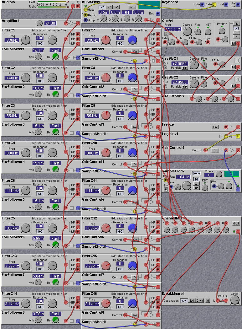
Figure 8.1. A vocoder made from bandpass filter modules. Includes features
such as spectrum sample/hold and freeze (K. v.d. Maarel).
The idea for the channel vocoder technique arises from the manner in which speech is generated in the human vocal tract. Simply put, the vocal chords produce a periodic, pulse-like, stream of air, which is then acoustically filtered by the elements of the vocal tract: the esophagus, tongue, lips, teeth, and the oral and nasal cavities. As one speaks different sounds, the shape and elastic properties of these elements are being constantly changed in response to neural signals arising from speech centres in the brain. This causes a time-varying filtering, or spectral variation, of the excitation arising from the vocal chords.
The channel vocoder, then, first analyzes the speech signal to estimate this time-varying spectral variation. To do this it uses the filters in the filter banks to determine how a particular frequency component of the speech signal is changing with time. On the output end, this analysis of the spectral variations are used to synthesize the speech signal by using another filter bank to apply these same spectral variations to an artificial periodic pulse like signal. The output filter bank acts as an artificial vocal track and the pulse signal acts as a set of artificial vocal chords.
Some sounds produced during speech do not arise from the vocal chords, but are produced by turbulent air flow near constrictions in the vocal tract such as may occur between the tongue and the teeth. For example, such sounds as "SSS", "K", "SSHH", "P", and so forth arise in this manner. These sounds would be poorly reconstructed using a pulse excitation source, and so most channel vocoders also have a noise signal that can be used as an excitation source as well. A "Voiced/Unvoiced" detector circuit is used to detect whether the speech signal is arising from vocal chord excitation (Voiced speech) or is arising from noise excitation (Unvoiced speech), and the appropriate excitation source is then selected at the output end.
Channel vocoders were originally developed for signal coding purposes, with an eye (ear?) towards reducing the amount of data that would be needed to be transmitted over communication channels. In fact, speech coding system development continues to this day to be a vigorous area of research and development. These systems have far outstripped the basic channel vocoder idea in complexity, coding efficiency, and intelligibilty, however. So why do we still care about channel vocoders? The reason is that channel vocoders (and the functionally equivalent, but computationally quite different, phase vocoder) have found application to music production. In the 1960's Siemens in Germany produced a vocoder which was used in some recordings. The BBC Radiophonic Workshop in England likewise pioneered the use of vocoders in recording and in radio and television. The vocoders used in these early musical efforts were very large and unsuited to general use. In the mid-70's a breakthrough of sorts came about when a number of companies, notably EMS (Electronic Music Studios) in England, produced relatively small and easy to use vocoders designed for use in musical applications. After that, the vocoder sound became a staple of the music and entertainment industry. Many extremely popular records (Kraftwerk!), TV shows (the Cylons of Battlestar-Galactica), and movies (Darth Vader in Star Wars) are identfied with vocoders. Although the introduction of these relatively small vocoding systems made it possible for the wide application of vocoders to music and film, they were still quite expensive for your average musician in the street. The EMS vocoder cost upwards of 6500 UK pounds! There are now, however, a number of inexpensive hardware vocoders available, as well as a few software emulators (including the world-famous Cylonix vocoder, developed by the yours truly).
The Nord Modular is also capable of implementing very nice vocoders. The following patch, developed by Kees van de Maarel, shows how to make an 8-band channel vocoder from the Nord Modular static filter modules. The quality of this vocoder implementation is nowhere near that of systems like the EMS vocoder, due to the relatively small number of bands and the slow cutoff rate (12dB) of the filters used. But the sound is still quite nice, and the patch illustrates the idea. It has a number of features not found on many cheaper vocoders - sampling and holding of the spectral features, and control of the speed of the envelope detectors. By slowing down the envelope detectors one can obtain a "slewing" effect where phonemes appear to get blurred together. This can produce a smoother sound.
Figure 8.1. A vocoder made from bandpass filter modules. Includes features
such as spectrum sample/hold and freeze (K. v.d. Maarel).
Of course, the Nord Modular also provides a self-contained vocoder module, so one does not have to go through all the trouble of constructing a vocoder patch from scratch, as in the patch shown earlier. The Vocoder module has a limited number of features, however, so there may still be some need to construct a custom vocoder patch. Some features can be added to the Vocoder module, however. For example, we show in the patch below how to add a Voiced/Unvoiced detection feature. In this patch the input signal is passed through two filters - a lowpass and a highpass, to estimate the frequency content of the input signal. If the lowpass filter output has an amplitude greater than the highpass filter output, then the input signal is mostly likely a pitched signal, such as a vowel sound. If, on the other hand, the highpass filter output has a higher amplitude then the input signal is most likely an unvoiced sound, such as a consonant. To do the decision as to the type of input signal we pass the filter outputs through envelope detectors (to estimate the amplitude of the filter outputs) and then compare the envelope detector output values. We use the output of the comparator module to switch, with a cross-fade module, between two signal sources - a mixed set of three square waves and a noise waveform.
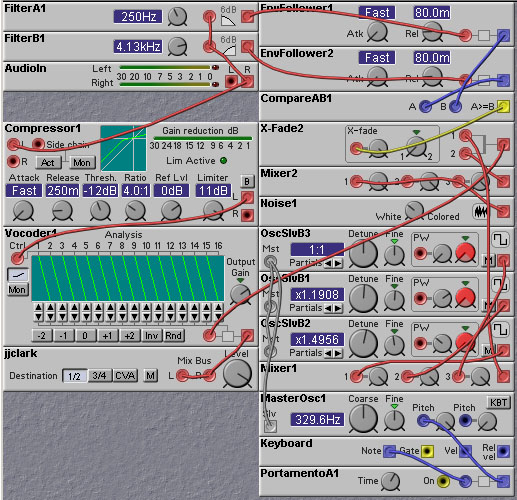
Figure 8.2. A vocoder patch made from the Nord Modular vocoder module.
Includes a voiced/unvoiced decision process to distinguish between
vowels and plosives (J. Clark).
Note the use of a compressor in the above patch. This is a common technique used with vocoders, as it prevents the sound from becoming too "choppy" due to the relatively low amplitude of vocal sounds at the beginning and end of spoken words.
The Nord Modular vocoder module allows the remapping of analysis channels to synthesis channels. This warping of the frequency content of a sound can be used in many ways; one of the most interesting being its effect on percussive sounds (try it!). It can also be used to make a male voice sound more feminine as crossing over some of the higher frequency bands can simulate the differences in the resonant structures of the male and female vocal tract. This is demonstrated in the following patch by Tommi Lindell.
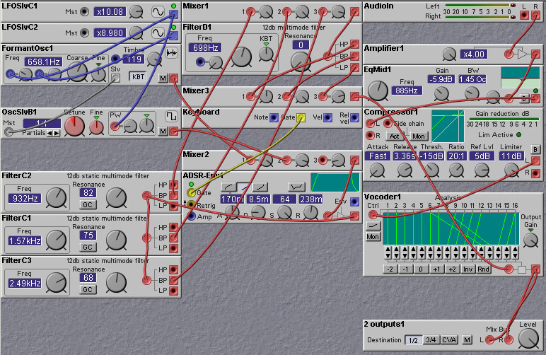
Figure 8.3. A patch that emulates female voices, with vibrato (T. Lindell).
There are four main forms of phonemes - vowels, diphthongs, semivowels, and consonants. We will examine the synthesis of each of these types of phonemes.
The vowel sounds are pitched and have a definite spectral structure. The vocal filter module is designed to produce the spectrum of vowel sounds. Vowel sounds are created by passing a periodic pulse waveform (which sets the basic pitch of the voice) through a complex filter with multiple resonances. The pulse waveform models the vibration of the vocal cords. In the patches below we use a narrow pulse wave, but half-wave rectified sine-waves and sawtooth waves could also be used. The complex filter models the effect of the vocal cavity, formed by the mouth, throat, and nasal passages. Because of the complicated shape of these passages, some frequencies are enhanced while others are diminished in strength. This results in resonances and anti-resonances. The resonances are known as formants. There are usually only three formants with a significant presence in vowel sounds. The first two formants play the biggest role in distinguishing one vowel sound from another. The center frequencies and bandwidths of these formants depend on the shape of the vocal tract. People can change this shape quite dramatically, mainly through changing the position of the tongue, resulting in large shifts of the formant frequencies. It is this shape-dependent shift of the formants that gives rise to the different vowel sounds. For some sounds, such as the vowel /a/ (as in "father"), the vocal tract is open at the front and constricted at the back by the tongue. In this case the frequency of the first formant is rather high and the frequency of the second formant is quite low. On the other hand, for sounds such as the vowel /i/ (as in "eve"), the tongue is raised towards the palate, constricting the front of the vocal tract while opening up the back. In these vowels, the first formant frequency is rather low, while the second formant frequency is high. Sounds like /uh/ (as in "but") are somewhere in the middle, with a relatively open vocal tract throughout.
The following patch is a demonstration of vowel sound creation. It uses
three bandpass filters to form the formants. Control sequencers are used
to adjust the formant frequencies (the sequencers are stepped on each
keypress).
Five different vowels are implemented -
ee - as in "beet"
eh - as in "bet"
ah - as in "bought"
oo - as in "boot"
uh - as in "but"

Figure 8.4. A patch illustrating the generation of five different
vowel sounds (J. Clark).
In the above patch the bandwidths of the bandpass filters were held constant. In reality, the bandwidths of the formants will change somewhat from vowel to vowel. If we wanted to go to that level of detail in our model, we could use a filter with a voltage controllable resonance level.
Some sounds are made by a rapid transition between two different vowels. Such sounds are called diphthongs. An example is shown in the following patch which generates a "aye" sound by sliding from the /a/ (as in "hot") vowel to the /i/ vowel. This is mainly implemented as a rise in the frequency of the second formant, and a slight drop in the first formant frequency.
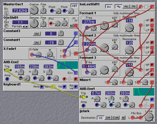
Figure 8.5. A patch that generates the diphthong "aye", by sliding
between two vowel sounds (J. Clark).
Note the use of the AHD envelope type in the patch above. These are convenient for speech synthesis for two reasons - they allow holding of the vowel for a certain length of time, and they have a trigger input rather than a gate input, which allows for repeatable timing when using a keyboard key press to begin the sound.
Related to diphthongs are so-called semivowels, such as /w/, /l/, /r/ and /y/. These are also created by a slide between two different phonemes as with diphthongs. The rate of the glide is somewhat slower than with the diphthongs. They can be difficult to synthesize, as they are often not even explicitly generated, but instead are inferred to exist between succesive two phonemes.
The following patch demonstrates the synthesis of a /w/ sound. This sound is not synthesized on its own, but instead arises when a glide between phonemes is created, starting from a /u/ sound. In the patch we follow the /w/ sound with a /ai/ diphthong to form a 3-way glide from /u/ to /a/ to /i/. The first glide creates the /w/ sound and the second glide creates the final vowel sound. The overall result is the sound "why". In general, any slide from /u/ to some other vowel will create a /w/ sound.
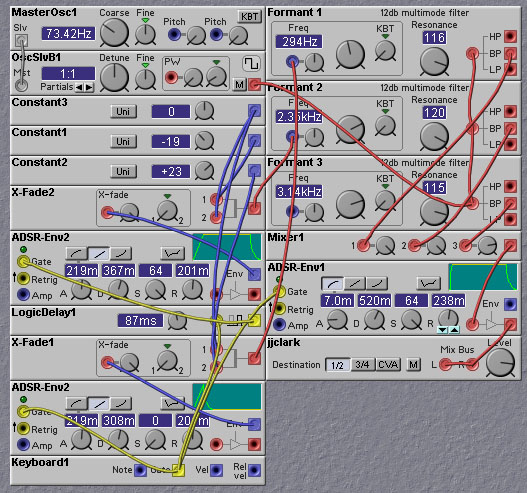
Figure 8.6. A patch that asks 'why' (J. Clark).
The next patch shows how to synthesize a "y" sound. Again, it is created by doing a slide from one vowel to another, in this case from the /i/ vowel to the /ae/ (as in "bat") vowel. In general, as slide from an /i/ vowel to any other will be heard as beginning with a /y/. This is almost the opposite of the "Aye" patch seen above.
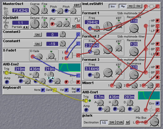
Figure 8.7. A patch that says 'yeah' (J. Clark).
The semivowel "r" can be made by sliding relatively slowly from the vowel /ir/ (as in "bird") to some other vowel. The /ir/ sound has a lowering of the 3rd formant frequency. This is due to the retroflexion (rounding) of the tongue. This is demonstrated in the following patch.
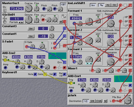
Figure 8.8. A patch that goes 'rah' (J. Clark).
Consonants are created when the vocal tract is constricted in some way, usually with the tongue, teeth or lips. There are five types of consonants employed in European languages - nasals, stops (voiced and unvoiced), fricatives (voiced and unvoiced), whisper, and affricates.
Stops are transient sounds created by the buildup and release of pressure behind a complete constriction somewhere in the vocal tract. There are three main types of stops, defined according to the location of the constriction of the vocal tract. In the alveolar stops /t/ and /d/, the constriction is formed by the tongue resting against the alveolar ridge behind the teeth. In the labial stops /p/ and /b/, the constriction is formed by the lips coming together. In velar stops /k/ and /g/ the constriction is created by pushing the back of the tongue against the soft palate (velum).
There are two forms of stops - voiced and unvoiced. These are distinguished by the presence (in unvoiced stops) or absence of an unvoiced excitation phase. In the unvoiced excitation phase, the vocal chords do not vibrate. Pressure builds up behind the closure site, and when the pressure is released there is a brief period of friction followed by a period of aspiration (steady stream of air passing through the vocal tract, exciting its resonances). In the voiced stops, the unvoiced excitation phase does not take place, and there is only a brief silent period.
Similar to the semivowels (/r/, /w/, /y/) the different voiced stops (/d/, /g/, /b/) are distinguished mainly by different shifts in the first two formant frequencies from a fixed locus to the frequencies associated with the following vowel. This shift in formant frequencies is caused by the changing configuration of the vocal tract from the initial closed form to the final vowel form. For /b/ sounds the second formant is initially in the range 600-800 Hz. For /g/ sounds F2 is initially around 1300 Hz, and is around 2KHz for /d/ sounds. In all stops the first formant frequency starts out very low and rises rapidly to that of the following vowel sound. There is also a brief percussive transient which has a broad spectrum falling off slightly with frequency. A brief silent period before the onset also emphasizes the consonant. The formant transition begins during the silent period.
The following patch illustrates the synthesis of the voiced stops /d/ and /b/. The patch says "daddy" and "babby", selected by knob 1.
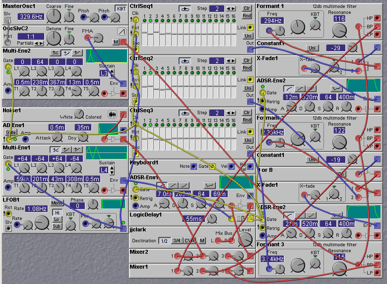
Figure 8.9. A patch demonstrating the synthesis of the
voiced stops 'd' and 'b' (J. Clark).
As mentioned above, unvoiced stops differ from voiced stops in that they have an unvoiced excitation phase consisting of a noise burst (due to the turbulent release of air past the constriction) and a brief period of aspiration(a sort of whispering sound). The nature of the different sounds obtained by having the constriction at different places is mainly manifest in the spectrum of the noise burst and aspiration. For /p/ sounds, made by a closure at the lips, the spectrum is concentrated at low frequencies. For /t/ sounds the spectrum is concentrated at high frequencies. For /k/ sounds, the spectrum has a shape somewhere between the /b/ and /t/ cases. The aspiration sound is created by passing a noise waveform with the same spectrum of the noise burst through the vocal tract filter. Thus, there will be formants in the aspiration spectrum, just as in the voiced excitation case. There is also the shift in formant frequencies to the following vowel as in the case of voiced excitation.
The following patch shows how unvoiced stops (as well as voiced stops) can be synthesized. Knob 1 selects the particular stop to be synthesized, and selects the appropriate noise spectrum and formant transition. Knob 2 switches between voiced and unvoiced synthesis, by gating in and out the unvoiced excitation.
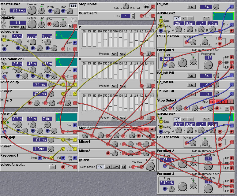
Figure 8.10. A patch demonstrating the synthesis of
voiced and unvoiced stops (J. Clark).
There are two types of fricatives, voiced and unvoiced. In unvoiced fricatives, the vocal tract is excited by a steady flow of air which becomes turbulent (noisy) in a constricted region of the vocal tract. The location of the constriction determines the nature of the resulting sound. For the fricative /f/ the constriction is at the lips, for /th/ sounds the constriction is at the teeth, for /s/ the constriction is near the middle of the oral cavity, and for /sh/ sounds the constriction is at the back of the oral cavity. The constriction divides the vocal tract into two sections. The sound radiates from the front part, and the back part traps energy and creates "anti-resonances" or dips in the overall spectrum of the sound. Fricatives that are made with the constriction near the front of the vocal tract have a broad spectrum, while those with the constriction near the rear have a more narrowly distributed spectrum.
The patch shown in the following figure shows how unvoiced fricatives can be implemented on the Nord Modular. Filter banks are used to sculpture the required spectral characteristics which distinguish the various types of fricatives.

Figure 8.11. Implementation of unvoiced fricatives. The patch
generates the sounds "Fee", "Thee" (unvoiced, like a lisped version of "See"),
"See", and "Shee". The spectrum
for each fricative is set by the filter banks.
Voiced fricatives are similar to the unvoiced ones, except that the vocal chords vibrate, causing a period pulsing of the air passing through the turbulence inducing constriction. The vocal chord vibration reduces the airflow, which lowers the amount of turbulence relative to the unvoiced fricatives. The patch shown in the next figure illustrates how we can implement voiced fricatives on the Nord Modular. This patch is essentially the same as the patch for generation of unvoiced fricatives. The major change is that the output of noise source modelling the turbulence is amplitude modulated by the oscillator modelling the vocal chord vibrations. This amplitude modulation simulates the pulsing of air through the turbulent constriction of the vocal tract.
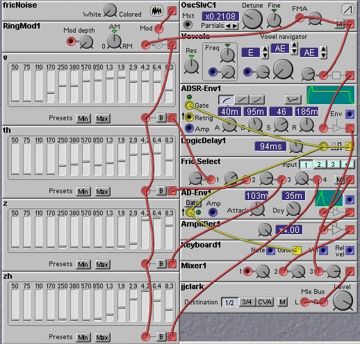
Figure 8.12. Implementation of voiced fricatives. The patch
generates the sounds "Vee", "Thee" (voiced), "Zee", and "Zhee". The spectrum
for each fricative is set by the filter banks.
Now you have most of what you need to make the Nord Modular say what you want (you might also want to find some tables of formant frequencies for the various vowels, these can be found on the net or in the library). You should tweak the formant frequencies, bandwidths, and envelope time constants to obtain just the sound you are looking for.
The following patches (by Kees van der Maarel) give examples of implementing various long utterances with the Nord Modular, combining vowels, semivowels, and consonants.
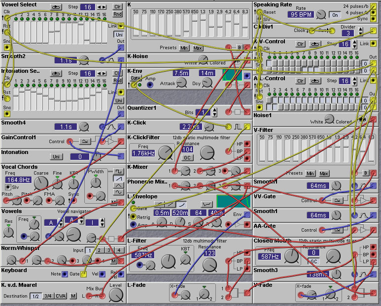
Figure 8.13. A talking patch. This one says 'Clavia'
(K. v.d. Maarel).
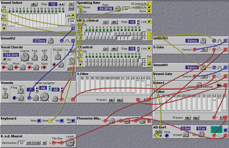
Figure 8.14 Another talking patch. This one says 'West'
(K. v.d. Maarel).
The first approach we will look at involves synchonization of an oscillator to the input signal. This uses oscillators whose waveform cycle can be reset by an external signal. Review the section on oscillator sync for more details. The following patch demonstrates this approach. In the patch an oscillator is synced to the zero crossings of an input signal. If the input signal is a relatively pure tone, the rate of its zero crossings will be more or less the same as its fundamental frequency. Hence the synced oscillator will track the pitch of the input.
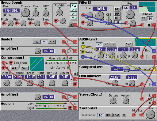
Figure 8.15. Another pitch follower patch. This uses an
oscillator synced to the zero crossings of the input signal (N. Beogh).
Rather than directly synchronizing an oscillator to the zero crossings of an input signal, we can instead measure the zero crossing rate of the input signal and use this rate measure to adjust the pitch of a slave oscillator. The following patch demonstrates this approach. A lowpass filter removes most of the energy of the input signal above 262 Hz. This is done to emphasize the fundamental frequency component, so that the zero crossings occur at the same rate as the fundamental. For most male speakers (and many female), the pitch of the voiced speech signals is less than 250 Hz. At each zero crossing a pulse of fixed width (1.3msec) is generated. These pulses are then smoothed out, or averaged, with a smoothing filter. This produces a control value which is proportional to the zero crossing rate. The control value is then used to vary the pitch of an oscillator, through the grey MST oscillator inputs (which provide linear frequency control).
One of the most common uses for a pitch tracker is to tune the carrier signal for a vocoder. In this way the vocoder can follow the pitch of the incoming signal. This avoids a 'robotic' sound, and is especially useful when you want to shift the apparent pitch of a sound (e.g. to make a male speaker sound female). Of course, sometimes you WANT the robotic sound, so in that case you should leave out the pitch tracking! The following patch illustrates how to use a pitch tracker in conjunction with a vocoder.
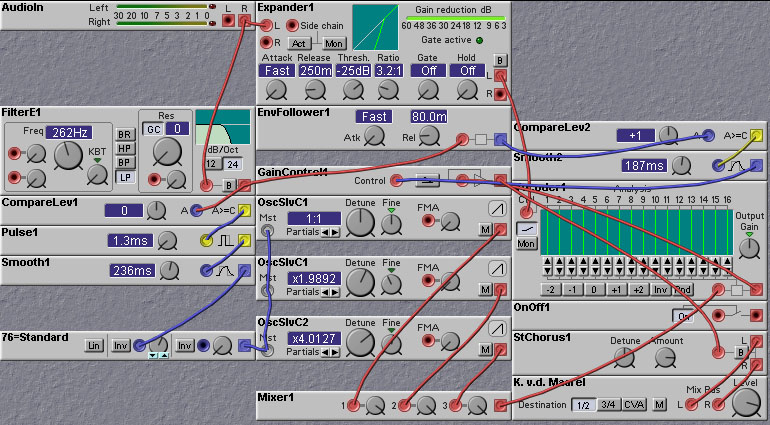
Figure 8.16. A pitch follower feeding into a vocoder (K. v.d. Maarel).
The final pitch tracking patch that we will look at uses a phase-locked-loop to track the pitch of the input. The phase-locked-loop is a circuit that is used extensively in communication systems, and in high-speed computer chips. Phase-locked-loops work by measuring the difference in phase between two signals - an input signal, and the output of an oscillator. The phase difference signal is smoothed with a lowpass filter and then used to change the frequency of the oscillator. If the phase difference is negative (phase of the oscillator lower than that of the input) the oscillator frequency is raised slightly, increasing the phase of the oscillator. This will tend to make the phase difference less negative. Similarly if the phase difference is positive (phase of the oscillator waveform is higher than that of the input signal) then the frequency of the oscillator is lowered slightly. When the phase difference is exactly zero, the oscillator frequency is held constant. In the following patch the phase comparator is implemented with a multiplier. The input signal is heavily amplified and clipped with an overdrive module to make it binary-valued (like a square wave). This binarised input is multiplied by the output of the tracking oscillator and the product is smoothed by the loop filter. In this design the phase-locked-loop tries to make the phase difference between the binarised input and the oscillator waveform 90 degrees. When the two signals are 90 degrees out of phase their product waveform (the output of the multiplier) will be half the time positive and half the time negative. Therefore the output of the loop filter, which averages out the multiplier output, will be zero (save for some ripple). If the input frequency rises, the phase difference will rise, and the output of the multiplier will have a duty cycle of more than 1/2, and the loop filter output will therefore also rise, causing the tracking oscillator frequency to rise. Similarly, when the input frequency drops, the phase difference will drop slightly causing the loop filter output to drop, resulting in a decrease in the frequency of the tracking oscillator.
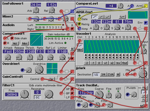
Figure 8.17. A phase-locked-loop pitch follower (J. Clark).
Pitch tracking can be used to control more than just the pitch of an oscillator. It can also be used to control filter cutoff, for example. Or even something non-frequency related, like the slope of an envelope generator attack (using a modulated enveloped generator module). The following two patches demonstrate such uses of a pitch track signal. The first uses the pitch track signal to control the cutoff frequency of a filter, the second to control the center frequency of a phaser module.
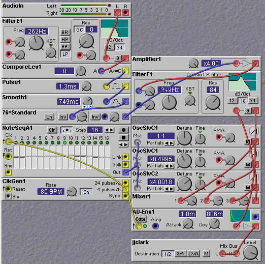
Figure 8.18. Using a pitch track signal to control filter cutoff
frequency (J. Clark).
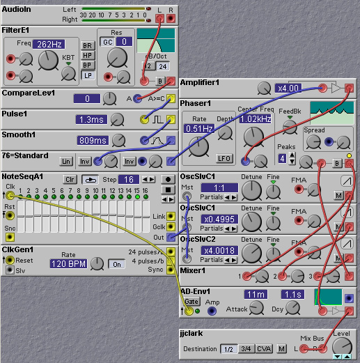
Figure 8.19. Using a pitch track signal to control the center
frequency of a phaser (J. Clark).
