Universal Logic Modules
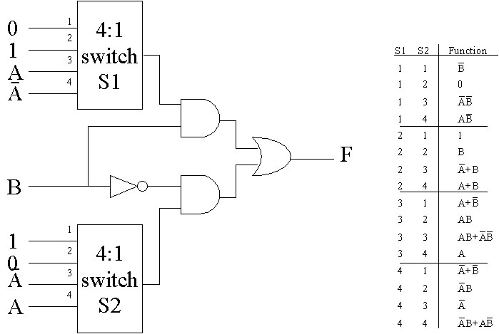
The Nord Modular provides only the most basic logic functions - AND, OR, XOR, and NOT (or Inversion). Fortunately, one can make any Boolean function (logic function) out of AND gates and NOT gates alone. In the following figure we show a "Universal Logic Module", which can implement any of the 16 different possible Boolean (logical) functions of 2 inputs. The different logical functions are selected with the two 1-of-4 switches, according to the table given in the figure.
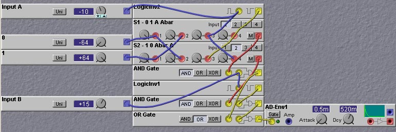
The universal logic module is easily implemented in the Nord Modular, as shown in the following patch. The envelope generator is used just for testing purposes; its gate LED can be used as a logic level indicator.
Multiplexers
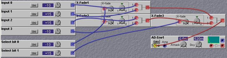
One of the more useful logic functions is the multiplexer. You can think of a multiplexer as a "voltage-controlled switch". A binary-encoded select input is used to choose one of a number of inputs and pass the value of the chosen input to the output. Although they could be formed from many logic gates, multiplexers are most easily implemented on the Nord Modular using X-Fade (Cross-Fader) modules. The following figure shows how to construct a 1-of-4 multiplexer on the Nord Modular. You could use these circuits in place of the 1-of-4 switches in the universal logic module patch, to obtain a voltage-controlled universal logic module. The multiplexer circuit works in a hierarchical fashion. The first select bit is fed into the fade control input of two X-Fade modules. This selects one of the two inputs to the X-Fade modules. The outputs of the 2 X-Fade modules are then fed into another X-Fade module. The fade input of this module is controlled by the second select bit. This circuit can be extended to larger numbers of inputs, by adding more levels. The number of levels that is needed is given by the logarithm base 2 of the number of inputs (rounded up to the next integral value). For example, if you had 12 inputs (which we do in the arpeggiator circuit described later in this chapter) you would need ceil(log_2(12))=4 levels. The last level always has one X-Fade module, the preceding level has two, and so on, increasing the number by a multiple of 2 for every level. Thus, for a 4-level circuit there would be a total of 1+2+4+8 = 15 X-Fade modules. Since, in our example, we only have 12 inputs, some (2 in this case) of the X-Fade modules in the first level can be deleted, as they will have no inputs.
Decoders
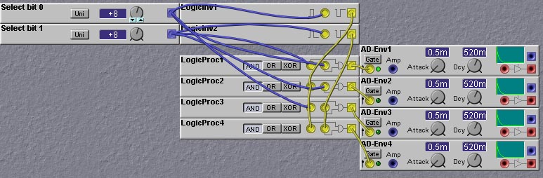
Another useful complex logic circuit is the Decoder circuit. This circuit takes in a binary input which is used to select which of a number of outputs will be set to a high level. All the other outputs are set to a low level. This can be used, for example, to select one of a number of oscillators or envelope generators to activate, or to choose a particular sample/hold module to sample. The patch shown in figure 9.4 shows how to make a 1-to-4 decoder on the Nord Modular.
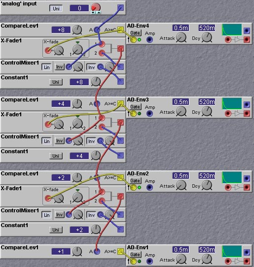
Analog to Digital Converters
In this chapter we are concentrating mainly on binary signals, which take on either a low or high value. This is the case for the yellow logic signals in the Nord Modular, but the blue and red (control and audio) signals have a wide range of possible values. It is sometimes useful to be able to convert from a binary coded version of a quantity (using a set of binary signals to encode the number) to an integer valued signal such as the control or audio signals. And vice-versa. We will refer to the process of converting the integer valued signal to its binary coded version as "Analog to Digital Conversion". Of course, all of the signals in the Nord Modular (apart from the signals at the input and output jacks) are digital, so this terminology is inaccurate at best. But it captures the spirit of what we are trying to do.
There are a number of ways to implement A-to-D conversion, borrowed from techniques used to implement real A-to-D circuits. One of these techniques is shown in the following figure. The figure shows a fully combinational logic (i.e. no memory elements) approach. The basic idea is as follows. The input value, to be converted, is compared with a value of 2^N, where N is the number of bits to use in the binary code of the output. If the input is greater than or equal to 2^N, we set the Most-Significant-Bit (MSB) of the output code to 1 and subtract 2^N from the input value. Otherwise we set the MSB to 0 and do not alter the input. We then take the (possibly altered) input and repeat the process, this time comparing it to the value of 2^(N-1). Again, if the (altered) input is greater than or equal to 2^(N-1) we set the value of the next MSB output to 1 and subtract 2^(N-1) from the input, otherwise set the next MSB to 0 and pass the input on unchanged. We continue in this fashion, level by level, until we reach a comparison with 2^(N-N)=1. The output of this comparison represents the Least-Significant-Bit. A 4-bit implementation of this approach on the Nord Modular is shown in the following figure.
Flipflops
The Nord Modular does not include a flipflop module, but we can make one using
the sample-hold module. This is shown in the following patch, which
implements a "toggle" flipflop. On each rising clock transition the
output of the flipflop alternates, or "toggles", between high and low
values. In the patch pressing the C4 key alternately turns the sound
on, and then off. This toggling action is very useful in a wide
variety of control tasks, and is also very useful in making so-called
"noodles" or auto-play patches.
One can use the sample/hold feedback approach to make a so-called "D"
flipflop (D is for "data"). A D-flipflop merely holds the value of its
input when the clock goes high. Now this seems to be the exact
operation performed by the sample/hold modules. So why do we need to
do anything else? Well there is a small problem, one that is actually
quite prevalent whenever you try to emulate parallel or concurrent
systems (such as analog synthesizers), in which every thing happens at
the same time, with digital systems where only a few things (or only
one thing) happen at a time. In the Nord Modular, on a single
DSP slot, operations are executed one at a time. This means that the
outputs of some modules are actually computed before the outputs of
others. Normally the order in which computations are done does not
matter. But sometimes it does, and in obtaining the proper functioning
of a D-flipflop is one of these times. To see this, consider a string
of sample/hold modules, intended to emulate a string of
D-flipflops. Such strings are referred to as shift registers
and are very useful. So encountering such a situation is not unlikely. Now
consider two adjacent sample/hold modules, where the output of one
feeds into the input of the other. Suppose that the operation is
synchronous, which means that every unit should change state at the
same time, usually in response to a clock signal transition. So let
both the of sample inputs of these two sample/hold modules be
connected to the same clock signal. Let the output of both sample/hold
modules be initially zero, and let the input to the first be connected
to a high signal. Now, what will happen when a rising transition of
the clock signal is received? Well, the answer depends on the order of
the computations! If the second sample/hold module is computed first,
everything will be OK. After all the computations are done, the output
of the first sample/hold will be high, and the output of the second
will remain low. But if the order of the computation is reversed, the
answer will be "wrong". Look carefully. If we compute the output of
the first sample/hold first, it will sample its input, which is high,
and therefore set its value to be high. Now we compute the output of
the second sample hold, but its input is now high, since we have
already computed the first module's output! Thus the output of the
second sample/hold module will also be high. This behaviour is bad for
two reasons. First is that sometimes we get the wrong answer. But
worse still, we can't say for sure when designing the patch whether we
will get the right answer or not, since we have no control over the
order of computation.
But we can design circuits that are insensitive to the order of
computation. We can use pairs of sample-hold modules that are clocked
with different signals, out of phase relative to each other. This
dual-phase clocking allows us to control when things
happen. The resulting circuit is called a "Master-Slave"
D-flipflop. The master is the first of the two sample/holds in the
pair, and the slave is the second, which merely follows the lead of
the master. A master-slave D-flipflop is shown in the following patch.
The patch shown above exhibits two different ways of clocking the
flipflop from a single clock signal. The first way is to clock the
first sample/hold module with the clock signal, and clock the second
with the inverse of the clock signal. This has the drawback that the
clock signal has to go high and then low again before the input value
appears at the output of the second sample/hold module. In many
situations, especially those in which the clock signal is a regular
periodic signal, this will cause no problem. In some situations, it
may be a long indeterminate time before the clocking signal goes
low. For example, in the above patch, to get a new value latched into
the D-flipflop one has to first press the C4 key and then release
it. It might be a long time before you release the key. It would be
preferable if the value could be stored in the flipflop whenever you press
on the key. In this case the second clocking technique may be better. In this
technique the clock signal is used to clock the first sample/hold as
before, but is also fed into a positive edge delay module to generate a
slightly delayed version of the clock signal. This delayed pulse is
used to clock the second sample/hold module. This will guarantee that
the first sample/hold module is clocked before the second. The delay
time is set to the minimum non-zero value of 1 millisecond. If the
clock rate is faster than 1KHz, this delay value will be too long and
the second sample/hold will never be clocked. In this case an
audio-rate delay line would have to be used. This is an expensive
solution, however, so in such high speed situations it is better to
use the first clocking technique and merely use an audio inverter to
invert the clock signal.
Counters
Counters are useful for many musical tasks. There are many different
ways to construct counters in the Nord Modular. Which way is best
depends on the application. Many sequencing tasks require counters,
and for these the ready-made sequencer modules fit the bill.
The control and note sequencer modules are very good for general
purpose counter design as well. They are easy to use and involve
merely setting the levels of the sequence step values to the desired
count values. For example, if you wanted to count repeatedly in the sequence
1,2,4,5,1,2,... you could take a control sequencer and set the loop
period to 4 and set the first four levels to 1,2,4 and 5. Voila!
Instant counter.
Using the sequencer modules as counters is an easy solution, but
sometimes one needs more flexibility. Often one requires a "binary"
output from the counter, where the count value is not in a "voltage"
but rather represented as a multiple-bit digital word. One could use a
"digital to analog converter" to convert a voltage level from a
sequencer module into a digital word, but this would be
inefficient. There are more straightforward techniques. One could
implement a binary counter directly using toggle flipflops, or even
D-flipflops, but unless you need to process audio-rate signals it is
more efficient to use ClkDiv modules.
If you need a binary counter that counts on its own at a certain constant
rate (rather than using an external clock signal) you can use synced
square-wave LFOs, whose frequencies are powers-of-2 multiples. The lowest
frequency square wave output is the Most-Significant-Bit (MSB), while the
highest frequency square wave output is the Least-Significant Bit (LSB).
Counters can be made with sample/hold modules feeding back to
themselves through summing (or mixing) modules. The output of the
sample/hold is added to a set value (say 1 or -1, for example) and the
sum fed back to the sample/hold input. When the sample/hold
is triggered, the new count value is loaded. This technique is used in
the patch shown below, an absolutely delightful classic created by
Keith Crosley:
In this patch, an "Up/Down" counter (one which can either count up or
count down) is formed from the sample/hold module labelled "Spring
Tensi.." and the summing modules labelled "+1" and "-1". Which of
these summing modules gets fed back to the sample/hold input
determines whether the counter counts up or counts down. The selection
of this feedback is done by the crossfade module labelled "+/-
Control", under the direction of the "Unwinder" signal derived from
the Squarewave LFO module labelled "Unwind Rate". When the phase of
the squarewave output of this LFO is high, the input to the
sample/hold comes from the "-1" summing module, turning the counter
into a down counter. When the LFO waveform is in its low phase the
counter is an up counter. This part is simple enough. The counter
alternates between being an up counter and a down counter following
the squarewave output of the "Unwind Rate" LFO. The actual
clocking of the counter, on the other hand, is somewhat more
complicated.
Asynchronous systems have been studied extensively by computer
engineers and many useful basic building blocks have been developed. One of
these building blocks is the "C-element". A C-element can be thought
of as an "AND-gate" for events. An event is generated on the output of
the C-element only after an event has been received on both of the
inputs. Thus, the C-element acts as a synchronizer - if an event
occurs on one of the inputs, the C-element will wait until an event
occurs on the other input before changing the output.
The symbol for an inverting C-element is shown in the following
figure, along with its truth table, and its implementation in the Nord
Modular using an XOR gate and Sample/Hold module.
The output of an inverting C-element is held whenever the inputs both
have the same value. If the values are different, the output is set to
the value of the A input (the non-inverting one).
C-elements are often used in control mechanisms for various
asynchronous operations. One example that is useful in music
applications is the asynchronous FIFO (first-in-first-out) buffer. In
an asynchronous FIFO events arrive (asynchronously) and stored in the
buffer, and then read out asynchronously. Think of the FIFO as a tube
in which one can insert balls in one end and can remove them out the
other end. Clearly the first ball in will be the first one out. There
is no need to put balls in at the same time you take them out, nor do
you have to do the insertion or removal at regular time intervals. Of
course, if the rate of insertion events is greater than the rate of
removal events, events will tend to pile up in the FIFO, which might
then overflow at some point.
The following diagram shows how such an asynchronous buffer can be
made out of inverting C-elements. This circuit was invented by Ivan
Sutherland, who termed it a micro-pipeline. The key aspect of this
buffer is the "hand-shaking" that is going on. Data is not just
crammed into the buffer indiscriminitely. Instead, the source of data
makes a "request" for data to be read into the buffer. This is done
by raising the Request_In control line to a high value. If the Ack_Out
line is low, then the request will be passed on, and the storage element
will be loaded (in this case the storage element is a sample/hold module).
If, on the other hand, the Ack_Out line is high, then the request will
be blocked, until such time as the Ack_Out line does go low.
The Request_Out line is connected to the Ack_In line, so that when
a request is honored, any requests upstream will be blocked until
the Request_In goes low again. In this way, a block at one point in
the buffer (usually at the last stage, where data is waiting to be
read out) will eventually propagate all the way to the first stage if
the last stage block lasts long enough for all of the buffer cells to
be loaded. If the last stage is being read out at a rapid enough rate,
there should be no blocking anywhere, and data loaded into the first
stage should quickly find its way to the last stage, where it is then
read out.
The following patch shows an implementation of a 16-stage asynchronous
FIFO buffer on the Nord Modular. The input events come from the keyboard
module, and hence are generated by the external world, perhaps by a
garage band drummer, and therefore not guaranteed to be periodic. The
output events are generated by a clock. Therefore this patch has the
effect of making the possibly irregular input events into a nice
smooth sequence (as long as the input events come in as fast, or
faster, than the output events, otherwise the outputs will stop). Of
course, one can just as easily do the opposite, where a regular
sequence of events is input to the buffer, while the readout events
are irregular. The last cell blocks until the readout clock occurs, at
which time the buffer is shifted by one place, and then resumes blocking.
As long as the read-outs occur more often than the input requests, the
buffer will never become full, and the input (first) stage will never
become blocked.
I will describe one particular implementation bit by bit. The patch
is loosely based on the Korg Mono/Poly arpeggiator. It works by
quickly scanning one octave of key detectors once during each
arpeggiation cycle.
Let us start by looking at the part of the patch that scans the octave
of keys. Twelve note-detect modules are used to detect the pressing of
each of the twelve keys in the octave. Each of these modules outputs a
high logic level when the corresponding key is pressed (based on
NOTE-ON commands in the MIDI stream input to the Nord Modular). We use
a counter to scan through each of the note-detect modules one by one.
The scan counter is implemented with a set of ClkDiv modules. The
outputs of the ClkDiv modules are passed through XOR gates which
permits the scanning to be either upwards or downwards. The XOR gates
either invert the counter outputs or leave them unchanged. The effect
of inverting the counter outputs is to have the counter count
downwards instead of upwards. The counter bits are used to control a
12-input multiplexer. A multiplexer is a circuit which selects one of
a set of inputs and passes that signal to the output. So here, the
scan counter selects which of the twelve NoteDetect module outputs to
examine. The multiplexer is implemented on the Nord Modular with a set
of CrossFader modules acting as binary analog switches. An expensive
solution perhaps, but in the absence of voltage-controlled switches on
the Nord Modular, the best we can do.
When the scan detects a key down (i.e. when the output of the scan
multiplexer goes high), the scan is halted until the arpeggiator clock
goes low, at which point the scan is restarted and searches for the
next key that is down. The envelope generators are triggered on the
rising edge of the arpeggiator clock. Let's pause here and look at an
example. Suppose there are three keys pressed, say the C#, F, and A
keys of the octave we are scanning. Suppose the scan counter is
counting up (we will look at up/down counting in a bit) from 0, which
corresponds to note C of the octave. The output of the scan
multiplexer will be low until the scan count reaches the count
selecting the NoteDetector tuned to C#. Then the output of the
multiplexer will go high. At this point the scan is stopped. Therefore
the multiplexer output will stay high. The desired operation of an
arpeggiator is to progress from one note to the next at times
specified by some arpeggiation clock. Thus we restart the scan when we
see the next rising edge of the arpeggiator clock. At this point the
scan will continue until the next key that is down is found, in this
case the F key. Then the scan stops again until the next rising edge
of the arpeggiator clock. You might complain that there will be a bit
of timing irregularity caused by the fact that there will be some time
elapsed after the rising of the arpeggiator clock to the detection of
the next key. So there will be a slight delay in the setting of the
pitch to the new value from when the envelope generators were
triggered by the arpeggiator clock. And you would be right, but the
scan clock frequency is set to be quite high, so that this time delay
is very small and unnoticeable in practice, and at worst adds a bit of
pitch modulation.
The key scanning process is the difficult and tricky part of the
arpeggiator design. The rest of the arpeggiator patch is just adding
in the bells and whistles which make arpeggiators so much fun.
As mentioned earlier, this arpeggiator is based on the one found on
the Korg Mono/Poly synthesizer, which had a number of different modes
of operation. The different features of the Nord Modulator
implementation are as follows:
9.2 Flipflops, Counters and Other Sequential Elements
The capabilities of logic circuits are greatly expanded if they contain
some form of storage or memory. Circuitry containg storage elements is
often refered to as "sequential logic" referring to the time dependent
behavior that such circuits posess. The memory can store intermediate results
or keep track of various counts, which can then be used to modify the
circuit's functioning in complicated ways.
In this section we will look at a few ways in which sequential logic
blocks can be implemented on the Nord Modular.
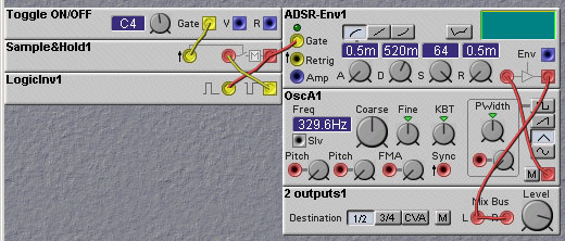
Figure 9.6. A toggle flipflop made using
sample-hold modules (R. Hordijk).
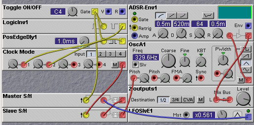
Figure 9.7. A master-slave flipflop made using
sample-hold modules (J. Clark).
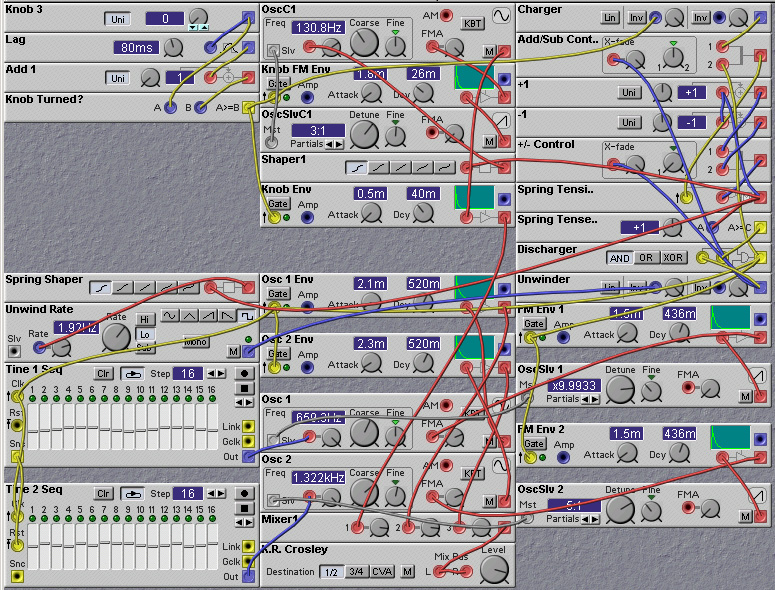
Figure 9.8. A patch simulating a wind-up toy. It contains many
different uses of the logic modules (K. Crosley).
9.3 Asynchronous Elements
Although most synth programmers are comfortable with sequential logic
elements such as counters, much of music cannot be tied to a rigid
clock. In fact, it is better to think of an electronic musical
instrument that is involved in a performance as an Event-Driven
system. In such a system, what drives transitions from one state to
the next is not the transitions of a clock signal, but the occurence
of an Event, usually generated externally to the system. For example,
events can be created by the pressing of a key on the keyboard of a
synthesizer, or the striking of a drumstick on an electronic drum
pad. As you are no doubt aware, even when playing music such as Bach,
where a very precise periodic rhythm is desired, the events produced
by human performers are by no means periodic. Some players are much
better than others, of course, but then there is the drummer from your
neighborhood garage band. Some music is arrhythmic. Some music has the
timing of its events derived from the environment. In all of these
cases, musical events essentially occur asynchronously, that is
to say, they occur independently of a periodic clock.
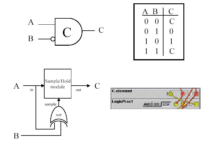
Figure 9.9. The (Inverting) Muller C-element. Upper-left:
graphical symbol. Upper-right: truth table. Lower-left: an
implementation using an XOR gate and a sample-hold
module. Lower-right: implementation using Nord Modular modules.
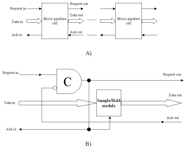
Figure 9.10. An asynchronous FIFO buffer made using
C-elements. a) A block diagram of the async FIFO consisting of chained
storage element blocks with asynchronous hand-shaking to control
transfer of data from one block to the next. b) Circuit for one of the
micro-pipeline blocks.
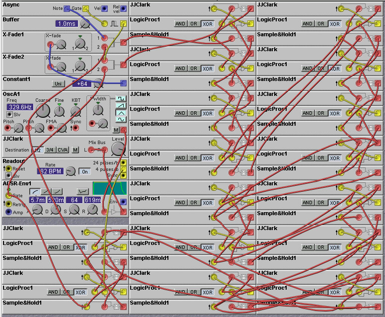
Figure 9.11. A 16-element asynchronous buffer Nord Modular patch
(J. Clark).
9.4 Arpeggiation
Constructing an arpeggiator in the Nord Modular (or in any modular,
for that matter) is deceptively difficult. It might seem that one just
needs to throw together some sample/holds and be done with it, but
things are not that simple. The main problem is that the order in
which notes are played in an arpeggiaton is usually in order of pitch,
rather than in order of being played. This means one can not just
store the sequence of notes (e.g in sample/hold modules) as they are
played. Instead one must scan the notes that are being played, in
pitch order. This scanning must be done continually, as notes can be
played or released at any time.
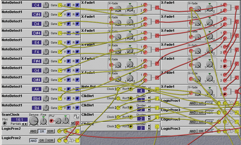
Figure 9.12. The portion of the arpeggiator patch that implements
the scanning of one octave of keys (J. Clark).
* The arpeggiation direction can be either UP, DOWN, or UP/DOWN. The
direction is set by the XOR gates acting the output of the scan
counter. In the UP/DOWN mode the input to the XOR gate is toggled
(alternated between high and low values) at the end of each 1 octave
scan. This toggling is implemented by a ClkDiv module acting on the
Most Significant Bit of the scan counter. LogicProc3 is an XOR gate
which combines the UP/DOWN toggle signal with the output of the "Up or
Down" switch, which selects whether the direction is UP or DOWN when
UP/DOWN mode is not active (i.e. when the "Up and Down" switch is
off).
* The arpeggiation pattern can be repeated in higher octaves. Either
1, 2 or 3 octave jumps can be selected. To see how this works, one
should first understand how the pitch is determined. The scan count at
the time when the scanning is stopped is converted to a pitch value by
a "digital-to-analog" converter, consisting of four multiplier modules
feeding a mixer. The multipliers multiply the counter bits by values
of 1,2,4, and 8, and these products are added together to complete the
conversion, and then fed into one of the pitch inputs of the master
oscillator. In addition to this pitch value, another pitch input of
the master oscillator is fed by an offset signal corresponding to the
octave jumps. The octave offets are values of
0,12,24 or 36, depending on the octave jump setting. The time at which
octave jumps are triggered is determined by the state of a counter
(implemented by the ClkDiv module titled OctRpt in the patch). This
selects the output of the octave jumps 1-4 switch. The period
of this counter is set by knob 7. It determines the number of notes
between jumps from one octave to the other. Interesting patterns can
be obtained by setting this period to something different than the
number of keys pressed.
In addition to the octave jumps, one can repeat notes within the
arpeggiation pattern. The number of repeats of a note is set by a
clock divider (the module entitled NoteRpt in the patch) placed in
front of the scan counter. This counter has the effect of pausing the
scan count until a given number of arpeggiator clock cycles have
passed, thereby resulting in the repetition of notes.
* There is a ping-pong pan mode which merely alternates successive
notes between the left and right outputs, giving the classic ping-pong
effect.
[Prev (Speech Synthesis and
Processing)][Next
(Algorithmic Composition)][Table of Contents]

(c) James Clark 2003