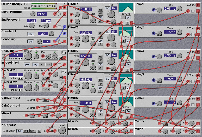
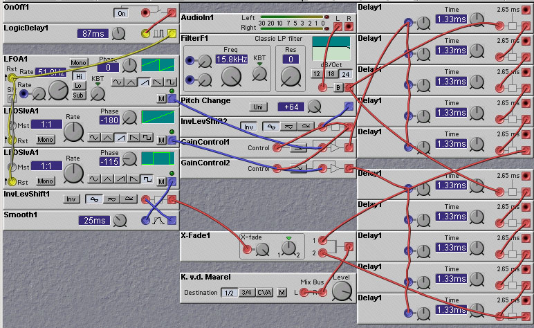
Figure 13.1. A 5-band spectrum shifter (R. Hordijk).
There are actually two forms of spectral shifting that are commonly encountered - pitchshifting and frequency shifting. These are related, but different, effects. With pitchshifting the frequencies of signal components retain their harmonic relationships. For example, a signal with a 1KHz fundamental and two harmonics at 2KHz and 5KHz, could be pitchshifted upwards by a factor of 2.5, and the signal components would now have frequencies of 2.5KHz, 5.0KHz, and 12.5KHz. The ratios of the frequencies of the signal components are seen to be the same as they were before the pitch shifting.
In frequency shifting, on the other hand, harmonic relationships between signal components are not preserved. To use the same example as before, if we shift our signal up in frequency (not pitch) by 1.5KHz, the resulting signal will have components whose frequencies are 2.5KHz, 3.5KHz, and 6.5KHz. The ratios of these frequencies are not the same as they were before the frequency shifting. The sound of a frequency shifted signal can be much different than that of a pitchshifted signal. But both techniques can give pleasing and musically useful results!
with Rob Hordijk
Spectrum shifting (technically called "single sideband modulation") can be done with two sinewave oscillators that are in quadrature (90 degrees out of phase), a phase-shifting allpass filter that shifts all frequencies 90 degrees with respect to the input, and a couple of ringmodulators. The ringmodulators multiply the two phaseshifted signals with the two sinewaves. The outputs of the ringmodulators are then summed. The effect is that all frequencies (=harmonics) are shifted up or down by a fixed number of Hz, this number being the frequency of the two sinewaves. This means that the stronger the effect the more the harmonics lose their harmonic relation. (This in contrast to pitch shifting!) So the effect is that you "morph" a sound between the dry sound and a "ringmodulation" effect sound at extreme shifts. A shift of a few Hz can e.g. make a static synthetic sound more lively. The difficulty in constructing such a frequency shifter is to make the phase-shifting filter (usually called a "Hilbert Transformer"). Such a filter usually only gives the desired phase-shifting properties over a limited frequency range. So, one must use a bank of bandpass filters, each followed by a phase-shifting filter giving approximately 90 degrees phaseshift for that band. If you use this multiple band approach you can make things really interesting if you start to randomly modulate the spectrum shifts in each band. This can give very beautiful "very big choir" chorus effects. If you use two spectrumshifters in each band, one shifting in the reversed direction of the other and mix those to left and right channels, the effect becomes very spatial as well. Professional effects units would employ thirty-three 1/3 octave bandpass filters, sixty-six spectrum shifters and thirty-three random modulators. (Actually one can modify a spectrum shifter to give two outputs, one shifted up and the other shifted down, so only 33 are needed). In addition you can give every band a randomly modulated delay of 10 msec with random predelays between 0 and 300msec for each band. This shifts the formants in time in relation to each other and thickens the effect even more. Its clear that you need a lot of DSP power and memory for the 33 delaylines to do this!
Some attempts by some people have been made to make a frequency shifter patch on the Nord Modular, but due to lack of a good allpass phase-shifting filter the results were not of very high "quality". Still interesting sounding, though. One such patch is shown below, designed by Rob Hordijk. This patch just shifts frequencies downwards. In order to shift frequencies upwards, you need to swap the outputs of the two quadrature sine wave oscillators (OscSlvFM1 and OscSlvFM2). With many more and much sharper filters the effect could be much more accurate, but the patch is especially nice with strings, female vocals (fun!) and brushed cymbals. Only the five frequency bands where the center frequencies are exactly 90 degrees out of phase get shifted by the required amounts, and the places in the spectrum where the phaseshifts do not match seem to come through slightly ringmodulated, which produces a tremolo with only minor shifts, giving some strange eerie phasing to sounds.
The following patch constructed by Tim Walters, shows a frequency shifter based on a Single-Sideband-Modulation (SSB) technique developed by Donald K. Weaver in the paper "A Third Method of Generation and Detection of Single-Sideband Signals", Proceedings of the IRE December, 1956, pages 1703-1705. A block diagram of the Weaver technique is shown below.
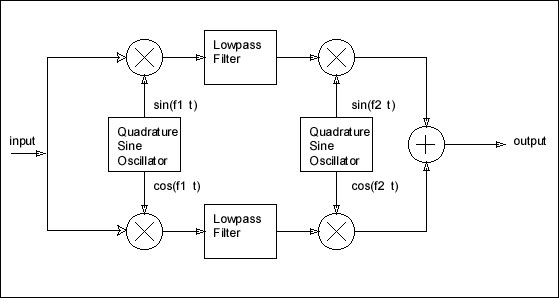
A nice description of how this circuit works is given in the article "An Efficient, Precise Frequency Shifter", by Jens Groh, in the CSound Magazine, summer 2000 issue. Unlike the spectrum shifting method described earlier, this approach does not need any phase shifting filters, but it needs four ringmodulators instead of two, and two quadrature oscillators instead of one. In Tim Walters' patch the quadrature oscillators were implemented with two LFOs, where the phases of the LFOs are adjusted to be 90 degrees apart.
The amount of frequency shift is equal to the absolute value of the difference between the frequencies of the quadrature oscillators. Does it make a difference which oscillator has the higher frequency? It makes no difference from the point of view of the amount of frequency shift, but it does make a difference to the type of aliasing error that is added by the shifting process. Usually this aliasing error will be minimal when the amount of frequency shift is small, but can be significant if the shifting is large. The lowpass filters should have a cutoff frequency equal to (or less than) to the frequency of the first quadrature oscillator. Both filters must have the exact same characteristics. The filters will limit the allowable frequency range of the input. Thus it is better to use as high a modulation frequency as we can. The maximum allowable modulation frequency is one quarter of the sampling rate (or 24KHz). In Tim Walters' original patch we can only get up to 392 Hz. This greatly limits the range of frequency shifts that we can obtain, as well as limiting the frequency range of the inputs.
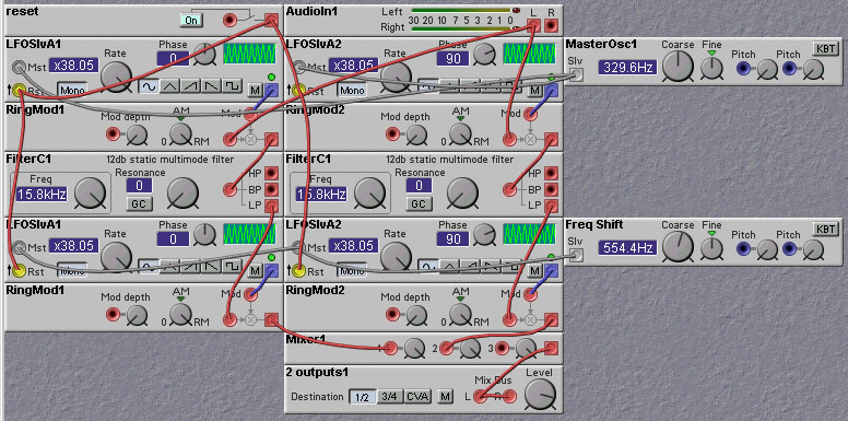
A phase-lock-loop (PLL) circuit can be implemented that will give a higher frequency quadrature oscillator with the Nord Modular modules. This approach is used in the patch shown below.
The phase shift of 90 degrees needed for the quadrature oscillator is obtained by taking two sin oscillators running at the same nominal frequency and modulating the frequency (and hence the phase) of one of them. The modulation signal is derived by multiplying the outputs of the two sinusoidal oscillators and lowpass filtering the product. If the two oscillator waveforms are exactly 90 degrees apart, with the same frequency, then the time average of their product will be zero. If there was a phase difference of less than 90 degrees the product would be greater than zero, and the frequency of the modulated oscillator would increase slightly, causing the phase difference to increase. Similarly, if the phase difference was greater than 90 degrees, the product would be less than zero and the frequency of the modulated oscillator would temporarily decrease, causing the phase difference to decrease. In both situations the phase difference will be forced towards 90 degrees, where it will remain, barring any noise or other disturbances.
Now, as a technique for counting trucks, this probably won't win you any praise for your boss, but it may help your chances in the Olympics. However, for purposes of music generation and processing, this trick comes in handy. In place of the tunnel, take the Nord Modular delayline module. It is like a tunnel where audio samples enter and exit instead of trucks. The output of the delayline is taken at a variable location along the delayline. So the output takes the place of the runner in the above tunnel analogy. Continually reducing the delay time (the location of the delayline readout) corresponds to the runner moving back down the tunnel. Thus we expect that reducing the delay time in this manner will increase the frequency of the signal being readout of the delay line. Similarly, if we steadily increase the delay time, the frequency of the signal being readout will decrease, just as in the case of the runner running towards the exit of the tunnel.
In order to get a constant increase (or decrease) in frequency, we will have to set the delay time back to its maximum once reaching zero delay (just as the runner did in using the teleportation device). In this case the increase in frequency effectively comes from a double "counting" (or double reading-out) of the audio samples in the delay line. This sudden shift back to the end of the delay line will usually result in a big discontinuity in the signal being read out of the delay line (as the value of the signal at the end of the delay line will usually not be the same as that at the beginning). One way to get around this problem is to multiply the output of the delayline by a triangle waveform whose value goes to zero at the beginning and end of the delayline. In this way the output goes to zero around the discontinuity point. Doing this, however, results in an "amplitude modulation" of the output, which will certainly not be desired. So, what to do? Well, you could use two outputs, at different locations along the delay line. This would be analogous to having two runners in the tunnel. If you spaced the output locations half the total delayline length apart, then one will have a maximum modulation when the other is at zero. So, if you added the two output values together, the modulations would cancel and disappear.
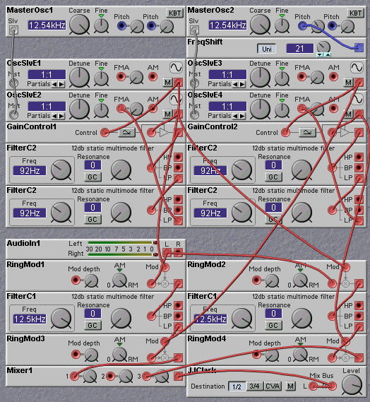
A Nord Modular patch, constructed by Kees van de Maarel, implementing this idea is shown below. This patch uses a rounded square-wave rather than a triangle wave to do the amplitude modulation.
The length of the delayline influences the quality a bit and that's why you can find optimization parameters for different intervals on the pitchshifter effects in the better effects machines. These parameters in effect set the length of the delayline (think of the phase differences between the waveforms from the two reading points) and the number of reading points (you need at least two, but you can imagine that using more reading points and different windows can increase the quality).
A vocoder can also be used to perform pitch shifting. In this approach, a signals spectral shape is analyzed and use to reconstruct a new signal with a different pitch. Details on this approach can be found in the Speech Synthesis and Processing chapter.
