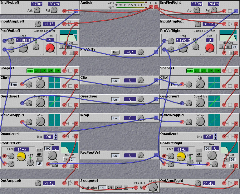
Figure 12.1. Serial distortion patch, including many different nonlinear modules to distort the input (W. Kemper).
Less common is the use of non-monotonic nonlinearities to create distortion. In the Nord Modular the WaveWrapper module is characterized by a non-monotonic nonlinearity. The distortion provided by this module is more extreme than that produced by the monotonic nonlinearities.
The following patch, designed by Wan Kemper, includes almost all Nord Modular modules that can distort audio signals, including the Shaper, Clip, Overdrive, WaveWrapper and Quantizer modules. These are strung in a series beginning with the most gentle distortion (the Shaper module) leading to more and more severe distortion (WaveWrapper and Quantizer). This ordering allows a wide range of distortion from subtle to radical.
The Nord Modular amplifier module can also produce a nice asymmetrical
clipping if it is overdriven, as can many other modules, such as the
mixer modules, and even the phaser module.
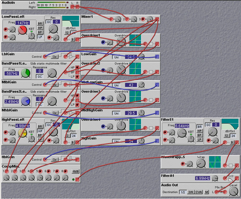
One of the most popular multi-band distortion units is the DIY (do-it-yourself) circuit known as the Quadrafuzz. This was designed by Craig Anderton and appears in his book "Projects for Guitarists" (GPI Books). A version of this circuit is manufactured (in kit form) by PAIA Electronics. The quadrafuzz, as its name would imply, splits the incoming signal into four bands, each approximately an octave in width. The outputs of each filter are passed through clipping style distortion circuits. The outputs of each distortion unit are then mixed together and passed through a final low pass filter. A Nord Modular implementation of the Quadrafuzz is shown in figure 12.2. It uses Overdrive modules rather than clipping modules and uses a lowpass filter for the lowest band and a highpass filter for the highest band, but otherwise the approach is very similar to the Anderton Quadrafuzz.
You don't want to take the multi-band distortion to extremes, however. It may seem like a good idea to use a large number of narrow bands and tailor the distortion for each band. The problem with this is that the harmonics that are generated are dominated by the harmonics of the filter band center frequencies, which are fixed, rather than the harmonics of the input frequencies. This leads to a rather static, hollow sound, akin to some vocoder sounds. It is an interesting effect in its own right, perhaps, but not what one would expect from a distortion effect. Thus, you should limit yourself to using a few bands, using rather broad filter banks. Although using a very large number of bands, say with an FFT-based harmonic re-synthesis approach might give a good result - a distortion with very little intermodulation components.
An effect related to distortion is the so-called "Exciter". This type of circuit aims to add harmonics to the sound in a way that does not sound like distortion, but rather as a restoration of high frequency detail that may have been filtered out somewhere along the line. Such circuits are often said to increase "presence" or "clarity" or add "sparkle" to sounds. The most famous of this type of effect is the Aphex Aural Exciter, which was first produced in the mid-70's. The Aphex effect highpass filters and phase shifts the input signal followed by a patented "Transient Discriminate Harmonics Generator" which creates varying amounts of harmonics depending on the dynamics of the input. Clearly, there are a lot of practical details left out of this description of the exciter's operation, and making a patch that duplicates the Aphex sound is challenging to say the least. But the basic idea, that of adding high frequency harmonics to the sound is not too hard to accomplish, as demonstrated with the following patches.
The first patch applies a highpass filter to the input signal and passes the filtered result to an overdrive module. The output of this distortion is then passed through another highpass filter, to allow selection of only the higher harmonics, if desired. The cutoff frequency of the two highpass filters are adjustable, thereby giving some control over the generation of the higher harmonics.
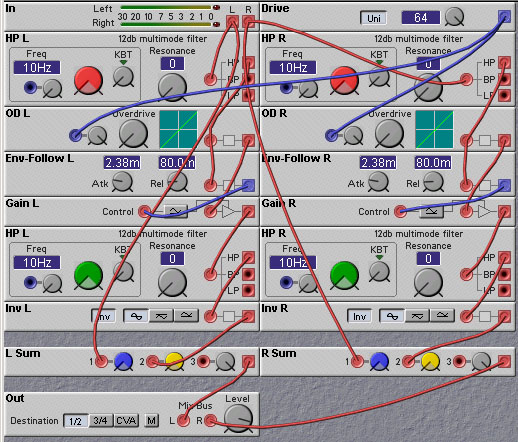
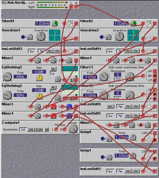
The second exciter patch is much like the first, but also contains a "big bottom" circuit, which aims to emphasize low frequencies sounds. The patch was designed by Rob Hordijk, who modeled it after the Behringer Enhancer. Aphex introduced the idea of the "big bottom" circuit as an addition to their exciter module. In the following patch the big bottom effect is obtained by adding a delayed version of a highpass filtered input (with a relatively low cutoff frequency) to the output. The delay does not affect the low frequencies very much (as they are not passed through by the highpass filter) but cause cancellations of some of the higher frequency components. This causes a perceived boost in the low frequencies relative to the higher, without affecting the overall amplitude significantly. This is important when driving amps or speakers that might not be able to handle extreme bass boosting or properly render sub-harmonics. Both of these exciter patches lack the (proprietary and secret) dynamics processing of the Aphex products.
A common criticism of "stomp-box" distortion units is that they don't sound very good when applied to synthesizer sounds. Some would take this to mean that the designers of distortion boxes just concentrate on getting them to sound good for guitars. Part of the problem is that guitar waveforms have some nice properties which permit good results to be obtained from applying distortion, properties which most synthesizer sounds don't have. These properties are: simple harmonic structure and smooth, controllable, decay. As we have noted above, the primary effect of distortion is to add harmonics. If a sound already has a lot of harmonics the distortion will just alter the level of the harmonics. If there are inharmonic frequency components, the harmonics added by distortion will tend to emphasize the inharmonic nature of the sound. Both of these effects will tend to result in a "harsh" sound.
We can do some things to improve the sound provided by passing a synthesizer sound through a distortion effect. The first of these is to restrict the harmonic structure by applying distortion separately to each voice in a polyphonic patch, rather than to the sum of all the voices. That is, you should apply distortion in the mono area rather than in the poly area. By summing the individual voices after distortion one avoids the intermodulation that you get if you summed the voices before distortion.
The creation of a fixed, finite, number of harmonics can be achieved with distortion functions whose input/output mapping can be expressed by a finite order polynomial. Chebyshev polynomials have the property that Tn(cos(theta)) = cos(n*theta). So if you make a linear combination of these polynomials, you keep a harmonic sound and you add frequencies in the spectrum.
You can find different Chebyshev's polynomials with the following
recurrence relations:
T0(t)= 1
T1(t)= t
Tn+1(t)-2*t*Tn(t)+Tn-1(t)=0
The kind of distortion created by passing an audio signal through
such a polynomial can be quite musical because it is not too harsh.
The limited nature of the nonlinearity means that the number of
intermodulation products is likewise minimized.
By adding together outputs of a number of different Chebyshev distortion units having different orders (eg. T0, T1, T2, etc), we can tailor how much of the various harmonic orders we obtain. This is useful in emulating various analog distortion modules. For example, in many tube amps, such as Marshall amps, distortion mainly produces even order harmonics, with odd orders coming in only at extremely high input levels. Some lower quality tube amps may have significant 3rd order harmonics. Push-pull tube amps can cancel out even order distortions, leaving mainly 3rd order harmonics. The solid-state "Fuzz-Face" distortion units distort asymmetrically resulting in significant 2nd order harmonics along with significant 3rd order harmonics, and some 4th and 5th order harmonics. The solid-state Electro-Harmonix Big-Muff PI circuit is symmetric and produces mainly 5th and 7th order harmonics.
The following patch illustrates how Chebyshev distortion can be implemented
on the Nord Modular. It implements a sum of the first four (counting from 0)
Chebyshev polynomials:
C(t) = T3(t)+T2(t)+T1(t)+T0(t) = (4t^3-3t)+(2t^2-1)+t+1.
It should therefore produce the first, second, and third harmonics of the
input signal, as well as passing the input signal itself.
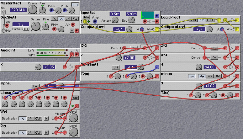
A problem with Chebychev distortion with the higher order polynomials is that, if you are not careful with signal levels in the patch, the multiplication operations can cause the some internal signals to become too large and be clipped. If this happens, more harmonics are generated than you want, and the sound can become muddy. In the patch shown above, an amplifier is used on the input to try to keep the internal levels low enough to prevent internal clipping. This amplifier (or attenuator) has the effect of reducing the dynamic range of the input signal, causing increased quantization noise, especially at low input levels.
Another problem is that the Chebyshev polynomials as defined by the recurrence relation given above only produce single, clean n-th harmonics if the amplitude of the input sinewave is exactly 1. A non-unit amplitude will result in more than one harmonic being generated. It is a good idea to try and limit the dynamic range of the input signal, for example using compression. In addition to creating more harmonics than the single one, a non-unit amplitude sinewave passed through an even-order Chebyshev distortion will also result in a DC component being added to the waveform. This DC offset may cause saturation or clipping, especially if the signal is fed back. Thus it may be a good idea to follow this type of distortion with a DC blocker, such as a high pass filter (with a very low cutoff frequency).
Another polynomial distortion
approach is to use X*ABS(X) instead of X^2, e.g. X-a(X*ABS(X)). It is
not a proper Chebyshev function but
yields a similar sonic result. The ABS (Absolute Value)
function can be conveniently made with a Diode module set to Full.
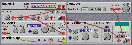
If the time-variation of the system parameters is periodic, and this period is a harmonic of the input signal fundamental frequency, then the output of the time-varying system will contain harmonic components. If the period of the time-varying system is not harmonically related to the input signal, or if the time-variation is not periodic, then the output signal will have non-harmonic components. While the creation of non-harmonic components may produce interesting results, it is not what is usually referred to as distortion, so we will not consider it further here. We will restrict our notion of distortion to be those systems which create new harmonics. Thus we will only look at time-variant systems where the time variation is periodic and related to the fundamental of the input signal.
You might argue that these systems are really nonlinear rather than linear, because the transfer function between the input and output can be written as a nonlinear function. And you would be right. But, nevertheless, it is often worthwhile thinking of systems as time-variant rather than nonlinear. Consider the following distortion patch in which the main signal path is directly through a linear element, in this case a filter. The filter cutoff frequency is varied by a control signal derived from the input signal. Since the time-variation is periodic (for a periodic input), the output of the system is harmonic, and by our definition, is a distorted version of the input signal. Try it on an external input signal, such as voice, and compare the results to other distortion techniques!