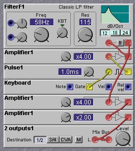
Figure 5.1. A simple bass drum patch (J. Clark).
Figure 5.1. A simple bass drum patch (J. Clark).
But bass drum sounds are actually somewhat more complex than those that this patch produces. The spectrum of a bass drum sound is harmonic at low frequencies (i.e. it consists of components with frequencies that are integer multiples), perhaps slightly shifted in frequency by 5-10 Hz or so, depending on how the drum is tuned. At higher frequencies the spectrum of the bass drum sound becomes more and more inharmonic. The sound produced by the bass drum consists of two parts - the vibrating drum head, and the sound of the mallet striking the drum head. This latter sound is very short and impulsive. The pitch of the drum's vibration increases when the drum membrane is struck, due to the increase in tension of the membrane. This causes an initial rapid rise in pitch, followed by a slower decay in pitch as the membrane relaxes.
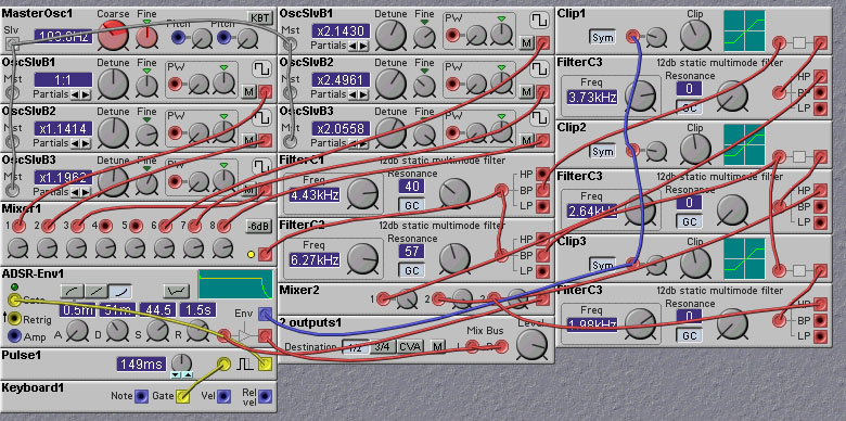
The following patch shows a rather complicated implementation of a bass drum. The low frequency components are produced by a master sine oscillator and a sinebank module containing six slave oscillators. The frequencies of these oscillators are adjusted to more or less correspond to the spectral components of a typical bass drum. The higher frequency, inharmonic, components are created by a pair of oscillators each frequency modulating the other. A short click is created by passing the keyboard gate signal through a pulse module. This produces the sound of the mallet hitting the drum. The overall amplitude of the sound is controlled with an AD envelope, with a very short attack and a relatively short decay. The envelope is also used to alter the pitch of the drum to mimic the change in pitch due to the stretching of the drum membrane when struck. Oscillator sync is used to ensure that the oscillator waveforms always start at the same phase when the attack begins.
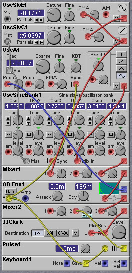
Figure 5.2. A rather complicated bass drum patch (J. Clark).
The following patch uses distortion to create harmonics from a low-frequency sinewave. A filter is used to tailor the spectrum. Distortion is applied before and after the filter for greater flexibility in the setting of harmonic levels. Separate envelopes are used for amplitude and pitch.
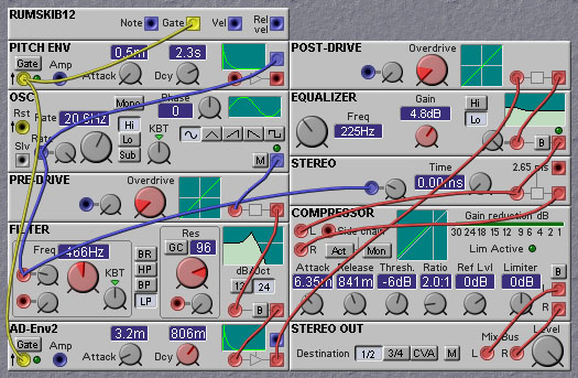
Figure 5.3. Another bass drum patch, which uses filter,
distortion and compression modules (P. G. Christensen).
If we just synthesized these resonant modes, our "snare drum" would sound sort of like a bass drum. It wouldn't sound much like a snare at all. To get the snare drum sound we have to also simulate the effects of the snare cables. Basically the snare cables act as resonant structures, which interact with the vibrating heads of the drum, through contact with the lower head. The cables are effectively one-dimensional structures and behave quite differently than the two dimensional drum head membranes. Thus the resonant modes of the snare cables are very different than those of the drum head membranes. The transfer of energy between the lower drum head and the snare cables will therefore be very complicated, almost random. To make matters even more complicated, the lower drumhead and the snare cables make physical contact in a nonlinear fashion (i.e. sometimes they are in contact, sometimes they are not). This nonlinearity causes all manner of inharmonic frequencies to be generated.
The upshot of the physical analysis of the snare drum is that it is very complicated, impossible to model exactly and impractical to implement even an approximate physical model on the Nord Modular. Instead, we take an empirical approach and try to capture essential features of the sound. There are two main parts to the sound - the basic (in)harmonic tone of the two vibrating drumheads, and the noisy sound caused by the snare cables. We could implement the drumhead sound in much the same way that we did for the bass drum. However, higher frequency components are mainly masked by the snare noise, so we can get away with just synthesizing the lowest frequency components. The following patch emulates the snare drum circuit in the Roland TR-909 drum machine. It uses two triangle oscillators to provide the basic drumhead vibratory modes. LFOs are used for this to save on processing power. The inaccuracies caused by the lower sampling rate of the LFO oscillators add a bit to the dirtyness of the sound. As in the TR-909, each oscillator has its own envelope. The lower frequency oscillator is given a slightly longer decay. The effect of the snare cables is emulated with a white noise source passed through a lowpass-highpass filter chain. The outputs of the low and high pass filters are passed through their own envelopes and then mixed together with the drumhead mode oscillator signals. The overall effect is rather plain, but definitely recognizable as a snare drum sound. The patch could be livened up by adding LFO control over the filter cutoff frequencies and applying distortion to the output. The mixing ratio between the snare noise component and the drumhead mode vibration component could be altered by key velocity, to emulate the natural effect of increased snare noise with striking force (since there is more interaction between the snare cables and the lower drumhead when the upper drumhead is struck more forecefully). I will leave it to you to try these enhancements!
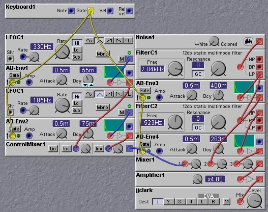
Figure 5.4. Snare drum patch based on the Roland TR-909 snare circuit (J. Clark).
Additive Synthesis
All periodic waveform generators produce harmonically related frequency components. One cannot, therefore, create inharmonic sounds directly using a single periodic waveform generator. There are a number of techniques for creating inharmonic waveforms. The most commonly used technique is additive synthesis which linearly adds two (or more) periodic waveforms that are detuned relative to each other. If the fundamental frequencies of the two waveforms are incommensurate (that is, they do not have any harmonics in common) then the resulting waveform will be aperiodic (it will never repeat exactly). An example would be with a wave of fundamental frequency 1, and another with fundamental frequency 1*square_root(2). In general, it is difficult to tune two oscillators to incommensurate frequencies. It is more likely that the two oscillators will have some rather high frequency harmonic in common. To make a convincing metallic sound, one needs to combine a large number of detuned waveforms, each tuned to frequencies incommensurate (or nearly so) with the others. For this reason, making inharmonic instruments via additive synthesis of this sort is tricky, but not impossible.
An example of using additive synthesis to get inharmonic sounds on the Nord Modular is shown in the figure below:
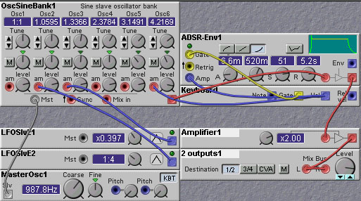
Figure 5.5. An additive synthesis approach to obtaining inharmonic
sounds (J. Clark).
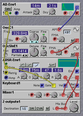
In this patch we use the sinebank slave oscillator module, which contains 6 separate sinewave oscillators. We set the relative frequency of the six oscillators to values which result in inharmonic frequencies. The amplitude of the second and third oscillators are modulated by two LFOs. This modulation provides some variation to the sound, making it more realistic. The envelope generator provides the bell-like amplitude dynamics.
Ring-Modulation
An easier way to get a lot of inharmonic frequencies is to use a nonlinear operation, instead of merely adding waveforms together. `Ring-modulation' is probably the most frequently used classic approach to generating inharmonic sounds. A ring-modulator essentially multiplies the two voltage waveforms together. This results in frequency components being generated which have frequencies equal to the pairwise sum and differences of each of the frequencies components contained in one waveform with each of those present in the second waveform. The original frequency components found in the two waveforms are suppressed and not found in the output. A modified version of the ring-modulator called the Amplitude modulator retains the original frequency components in addition to the new components. For example, if waveform 1 has components with frequencies of 1KHz and 1.2 KHz, and waveform 2 has components with frequencies of 2.7KHz, and 3.3 KHz, then the ring-modulated waveform will have components with frequencies of 1.7KHz (2.7-1), 3.7KHz (2.7+1), 2.3KHz (3.3-1), 4.3 KHz (3.3+1), 1.5KHz (2.7-1.2), 3.9KHz (2.7+1.2), 2.1KHz (3.3-1.2) and 4.5KHz (3.3+2.2).
If the fundamental frequencies of the two waveforms input to a ring-modulator are incommensurate, or nearly so, the set of sum and difference frequencies that are generated will be inharmonic. The advantage of using a ring-modulator over merely adding two waveforms is that the number of distinct frequency components that are generated is much greater. For example, if the two waveforms have 3 harmonics each, adding the two waveforms will yield 6 components, while ring-modulating will yield 18 components. For more complex waveforms, with richer spectra, the difference will be even more pronounced. This efficiency in generating inharmonic spectral components is the main reason ring-modulation has found so much use in generating metallic sounds in synthesizers.
In the Nord Modular, ring-modulation is easy to do. There is now a ring-modulator module, which can also be adjusted to provide amplitude modulation (which leaves the original spectral components). One can also use the controllable amplifier to do ring-modulator (and this is how it was done before the OS upgrade that gave us the ring-modulator module).
An example of using ring-modulation to create inharmonic sounds on the Nord Modular is shown in the following figure:
Even though a single ring-modulator can give us a very rich inharmonic spectrum, we need not stop there! Connecting two ringmodulators in a row with only slightly detuned sinewaves gives a nice detuning effect like the big double gamelan gongs in addition to the ring-modulation effect. To make that a stereo effect we can use four. The detuning can be done by feeding only a slight constant value to the FMA inputs, one sine oscillator a negative value and the other a positive value. The advantage of using the FMA inputs is that the detune amount stays constant over the frequency range. To make a more realistic sound, one can follow the ring-modulators with a resonant filter, or delay line based `tube'. The frequency of the oscillators in combination with the frequency of the 'resonating body' controls the timbre of the metallic sound. Keeping the frequencies not too high is best for replicating the bronze sound of gongs. Using sawwaves or squarewaves instead of sinewaves can also provide richer sounds..
FM Synthesis
The other most commonly used technique for obtaining inharmonic waveforms is frequency modulation (FM). Frequency modulation is a technique for non-linearly combining two waveforms. One waveform is used to vary the frequency (or the phase) of the other. The resulting spectrum is very complex and generally contains an infinite number of harmonics.
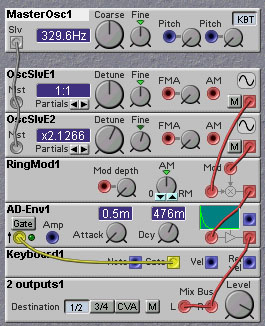
Implementing FM on the Nord Modular is very straightforward, thanks to the frequency modulation inputs on the slave oscillator modules. A simple FM bell patch is shown below:
In this patch a master oscillator is used to provide both a fixed frequency reference for the slave oscillator as well as a frequency modulation signal for the slave oscillator. The nominal ratio of the slave oscillator frequency to that of the master is set to a non-integer value, which will result in inharmonic frequency components in the output of the slave oscillator. The first envelope generator modulates the amplitude of the master oscillator output. As the master output is used to frequency modulate the slave, increasing its amplitude results in a brighter sound for the slave output, with more frequency components. Thus, this envelope generator acts very much like a filter envelope in a standard subtractive synthesis patch. The second envelope generator is used to provide the overall amplitude dynamics associated with bell-like sounds. The initial `blip' or transient models the striking of the bell.
Cymbal Synthesis
As mentioned earlier, perhaps the most difficult instrument to get right is the cymbal. Its sound is very complex. It contains inharmonically related frequency components, but unlike other metallic instruments, these components are not pure sinusoids, but rather components that are somewhat spread in frequency. These "wide-band" frequency components give the cymbal its noisy sound, and in fact noise can be used to spread the frequency components of a sinusoidal oscillator. To see how we can begin trying to synthesize a cymbal, examine the following patch:
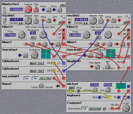
In this patch, we use two sinusoidal oscillators which are frequency modulated by noise sources. This modulation spreads the bandwidth of the single frequency component of the sine wave oscillators, producing a form of "pitched noise". We want the variation of the two oscillators to be somewhat uncorrelated, so we produce two different noise signals. To make sure the noise sources are different we use two clock noise sources and clock one with a noise signal and clock the other with the inverse of the noise signal. In general, the timing of the rising and falling edges of a noise signal will be uncorrelated, so this will give us what we want. (to make this need for de-correlation obvious, try modifying the patch to connect the same noise signal to both oscillators - the sound is much less random).
The nominal frequencies of the two oscillators are set to inharmonic intervals. The master oscillator should be set to a fairly high frequency (5-7 Khz works well). The outputs of the oscillators are sent through bandpass filters and then through overdrive modules which distort the waveforms, thereby generating additional harmonics. The outputs of the overdrive module are fedback to mixers, which combine with the opposite pre-overdrive signals. The outputs of the mixers are then ring-modulated. This ring-modulation produces even more inharmonicity.
The cymbal patch given above is far from realistic, and perhaps is only useful for a hi-hat buried in the mix. There are many analog drum machines, such as the Roland TR-808 that do a decent job of synthesizing cymbal sounds. Robin Whittle (the maker of the TB-303 Devilfish mod) posted a message on the music-dsp mailing list on how the TR-808 cymbal sound is created. He writes:
"The Roland TR-808 drum machine uses six audio square-wave oscillators, all mixed together with no precise tuning. These are mixed together and used as the input of two separate bandpass filters. The output of one bandpass filter drives one "gating" circuit. The output of the other drives two "gating" circuits.
Each gating circuit is an inspired concoction of transistors, diodes, resistors and capacitors which distorts the signal - imagine limiting a wide ranging signal between two limits, so it is basically a square- wave, and then changing the limits to control the volume. The three gate circuits have various time-constants for their volume.
Their outputs go into three separate high-pass filters, whose outputs are summed to produce the final signal."
The Nord Modular patch shown below is a (perhaps not entirely accurate) implementation of this approach.
This patch produces a much more realistic cymbal sound, although still far from perfect. One of the limitations of this patch has to do with the limited frequency range of the Nord Modular. Even though we can't hear frequencies above 20KHz (or not even that high!) the cymbal vibration includes many frequencies above this limit. These high frequency components can then interact nonlinearly with each other which can generate sum and difference frequencies just as in ring-modulation. While the individual frequency components might be too high in pitch to hear, their difference frequencies may be audible. The Nord Modular cannot replicate these effects, and so the complex variation of a real cymbal will not be captured.
Physical modeling has also been suggested as a way to synthesize cymbal sounds. In contrast to the physical modeling approach to synthesizing woodwind and stringed instruments, which use one-dimensional digital waveguides, physical modeling of cymbals requires the use of two- (or even three-) dimensional digital waveguides. While, one could conceivably implement two-dimensional waveguides with the Nord Modular (by constructing two coupled one-dimensional waveguides), accurate synthesis of cymbals would require a very large number of elements. The distinctive sound of the cymbal comes in large part from the grooves and ridges embossed on its surfaces. These influence the propagation of and reflection of waves along the surface. The propagation velocity, which determines the frequencies of individual waves, varies nonlinearly with the stress at each point in the cymbal. To model accurately, one would need nonlinear waveguide segments for each of these grooves and ridges. Thus hundreds, if not thousands, of delay line elements would be needed, something which is not possible with the current version of the Nord Modular.
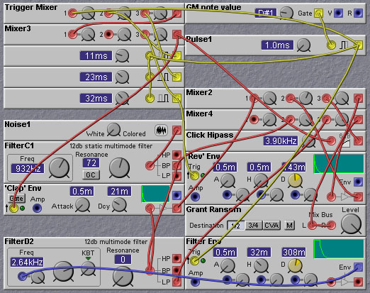
Figure 5.10. A patch for generating hand clap sounds (G. Ransom).
In this patch, white noise is amplitude modulated by a fast envelope to create the direct hand clap impulse. The envelope is triggered by a series of four pulses, each about 11 msec apart.
I will leave it as an exercise for the reader to synthesize the sound of one hand clapping!
