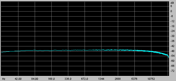
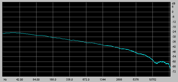
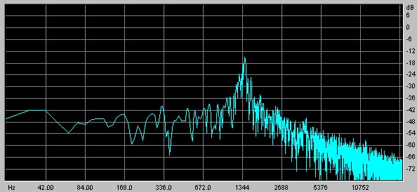
Figure 4.1. White noise spectrum.
White Noise
In its oscillator section, the Nord Modular contains a white noise module. The waveform produced by this module has a flat spectrum, out to about 20KHz. That is, the waveform contains frequency components of equal amplitude over this range. The spectrum is shown in the following figure.
(Note: this spectral plot, and other plots which follow, was obtained by digitizing the output of the Nord Modular feeding through a Mackie 1402 mixer, with a 20-bit Event Gina audio card. The spectrum was computed by CoolEdit Pro, in 32-bit mode.)
Pink noise is `self-similar' in that if you increase its time scale by a factor of 2, it looks the same (in a statistical sense). This self-similarity property has inspired many applications to random compositions, where the micro-structure of the piece (e.g. individual notes) are mirrored by its macro-structure (e.g. thematic variations). For this reason, as well as the fact that it sounds more uniform than white noise, pink noise is very useful in music.
At first glance, it may appear simple to generate pink noise. All we have to do is filter white noise with a lowpass filter having a falloff of 3dB/octave. Well, yes, but you might notice that the Nord Modular does not include a filter with a 3dB/octave falloff. In fact, the first order filter has a 6dB/octave falloff. We need a 1/2 order filter! Or so it seems. Fortunately, there are a couple of tricks that we can play to get a filter with a 3dB/octave falloff, or to generate a noise directly that has the desired spectrum.
The first approach is due to R. Voss, and was described in a Scientific American article by Martin Gardner (M. Gardner, "White and Brown Music, Fractal Curves and One-Over-f Fluctuations", Sci.Amer., 16 (1978) p.288). The idea behind this approach is to sum the output of a sequence of clocked white noise generators, each being clocked a factor of two slower than the preceding one. The clocking can be thought of as a sample/hold operation on the output of a continuous white noise generator. The holding process has the effect of lowpass filtering the noise signal. The lower the clocking rate is, the lower the effective cutoff frequency of these lowpass filters. Summing the outputs of the sample/hold units then yields an overall frequency falloff with the desired 3dB/octave value.
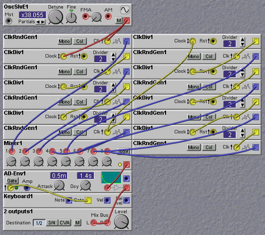
The Nord Modular has exactly the module that we need for this process, the ClkRndGen module. This module acts like a sample/hold being applied to the output of a white noise generator. The pink noise generation patch using these modules is shown below:
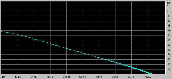
The spectrum of the noise generated by this patch is shown in the following graph:
The spectrum is not perfectly straight, as you can see flat spots. The average falloff is approximately 3dB/octave, over the range of 30-3000 Hz or so.
A second approach to obtaining pink noise is to sum the weighted outputs of a set of first order (6dB/octave) lowpass filters being fed white noise. If the cutoff frequencies and weights are chosen properly, then the overall spectrum will have the desired 3dB/octave falloff. A Nord Modular patch based on this approach is shown below.
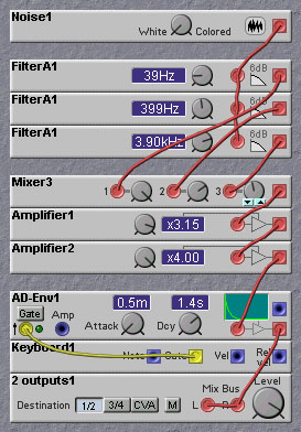
Only three filters are used in this patch. More accurate results (with less ripple in the falloff) can be obtained with more filters. The cutoff frequencies of the filters are set to be multiples of 10 apart (30 Hz, 300 Hz, 3000 Hz), and the weights of the summing operation were chosen by trial and error to give the desired response. The spectrum of the noise generated by this patch is shown in the following graph:
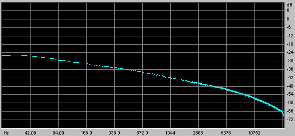
Note that the falloff is smoother than that obtained with the summed ClkRndGen approach. The range of frequencies where the falloff is about 3dB/octave is about the same, however. The falloff rate begins to increase past about 6 KHz.
There is a wide range of different approaches to generating pitched noise. We will cover a few of these here.
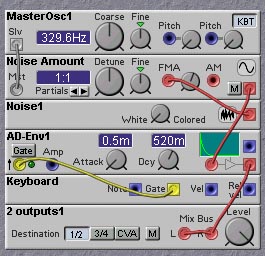
One way of producing pitched noise is to modulate an oscillator with a noise signal. The modulation will spread the spectral peaks of the oscillator. The following patch uses frequency modulation of a sinewave oscillator by a white noise signal.
The spectrum of the noise generated by this patch is shown in the following graph:
Note the presence of one main peak that is quite wide. The noise modulation has broadened the very sharp peak of the sinewave oscillator. As one increases the modulation amount, the width of the peak increases and the sound becomes less pitched.
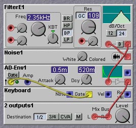
Another approach to generating pitched noise is to pass a noise signal through a resonant bandpass filter. The filter will preferentially pass frequencies near the filter's resonant peak, causing a noise spectrum similar to the one obtained with the FM technique shown above. The width of the peak can be adjusted with the filter's resonance control. The higher the resonance, the narrower the peak, and hence the more pitched the sound becomes.
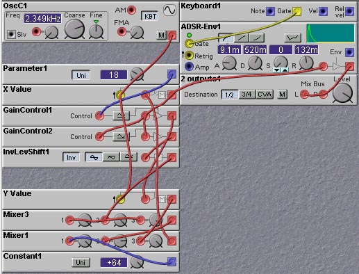
Chaotic systems can also be used to create pitched noise. We won't go into the details of chaos here, but you can read the chapter on chaos to learn the ideas underlying chaotic systems. The following patch uses a chaotic system of the Henon type. The oscillator is used to clock the dynamic system to go from one state to the next. This clocking gives the sound its basic pitch. The chaotic behaviour of the system gives the sound its noisy aspect. Adjusting the level of the Parameter1 setting causes the system to move between chaotic and non-chaotic (period) regimes. Different types of sounds are obtained in this way, so experiment!
Note carefully that in this patch there are no noise source modules at all, just an oscillator and some multipliers and adder modules. Even so, noise appears! Such is the power of chaotic systems - even simple systems can exhibit very complex behaviour.
The spectrum of the noise generated by this patch is shown in the following graph:
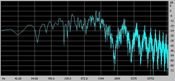
The spectrum is more or less flat until the frequency approaches that of the clocking oscillator, at which point the spectrum drops rapidly to a minimum. After this point, the spectrum exhibits a shape similar to a noisy square wave oscillator.
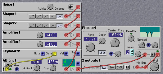
Another useful technique for altering the spectrum of noise is to pass white noise through a nonlinearity such as the shaper module. If the shaper is set to exponential (curving up) it enhances the peaks and suppresses the valleys in the noise waveform. This makes the noise signal more `spiky'. Try using such an expanded noise signal to excite a filter module. Using a single filter with high resonance only excites a single particular frequency. The phaser module and the vowel filter can resonate on more frequencies at the same time. The phaser seems to create the most interesting result, a bit like stroking a hard brush at the side of a metal sheet. An example of this is shown in the following patch which implements a 'shaker' or maracas.