Next: phb
Up: Function Reference
Previous: Function Reference
Contents
Purpose
Create (declare) Lie algebra generators and control inputs.
Syntax
createLBobjects(nGen,sLen);
Description
This function creates the symbolic variables representing the Lie
algebra generators and the control inputs. The function assumes the
variables do not exist, so if the variables exists, they will be
replaced by the new ones, with the corresponding assumptions without
warning to the user. Adding a line to check for the existence of
already assigned variables is simple and can be done as for the
function phb. In general, however, verifying variables
redefinition should not be really necessary since the amount of
variables regarding a particular problem or system is directly related
to the system model, which should only be changed at the time of
declaring the system generators and inputs and not at some
intermediate step of the symbolic manipulations.
|
Arguments
 Number of Lie algebra generators.
Examples
Declaration of vector fields for a system with drift, 2 inputs and a
sequence of control inputs of length 4 (i.e. four switches).
> createLBobjects(3,4);
Generators Input Sequences
f0~ u0_1~ u0_2~ u0_3~ u0_4~
f1~ u1_1~ u1_2~ u1_3~ u1_4~
f2~ u2_1~ u2_2~ u2_3~ u2_4~
Span of Generators for each segment of the control sequence
f_1:=f0*u0_1+f1*u1_1+f2*u2_1
f_2:=f0*u0_2+f1*u1_2+f2*u2_2
f_3:=f0*u0_3+f1*u1_3+f2*u2_3
f_4:=f0*u0_4+f1*u1_4+f2*u2_4
|
Discussion
In the above example, f0, f1, f2 represent the vector fields
which generate the Lie algebra. The tilde ~ symbol at the end
of each variable indicates that some assumptions have been made on
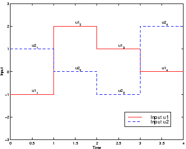
these variables. The ``subindex'' _i, after each variable
var indicates the corresponding time interval,
thus the expression var_i corresponds to the particular
value of var in the time interval i of the input
sequence. An arbitrary input sequence with 4 switches is illustrated
in Fig. 6.1.
|
		Figure 2:
Control inputs sequence.
|
|
Notes
Notice that the the system in the example is drift-free, however
it is possible to obtain a system with drift by simply setting the
controls u0 to 1. This can be easily achieved with the Maple command
subs for substituting expressions.
|
Limitations
The current implementation does not allow to select a name for the
generators or controls which are set to f and u,
respectively.
|
Bugs
In the current implementation the controls u are assumed to be
of type real, even if they could be in any other field from the
theoretical point of view. The reason for this is an apparent bug
in Maple which returns true for the command is(x,scalar) for
any x, even if x is assumed to be of type vector! Thus
assuming x of type scalar causes a problem, since a generator
of vector type will also be regarded by Maple as scalar and the
simplification routines will fail to recognize it as a generator.
To circumvent this problem, for the moment we use type real when we
mean scalar, and type vector for the generators.
|
Next: phb
Up: Function Reference
Previous: Function Reference
Contents
Miguel Attilio Torres-Torriti
2004-05-31