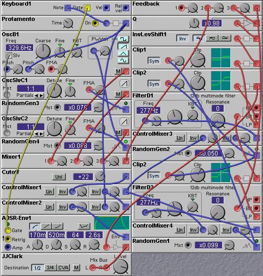
Figure 3.1. Resonant filter oscillator patch (J. Clark).
The Classic filter on the Nord Modular can be made to oscillate if its resonance setting is high enough. The frequency of the oscillation is the same as the cutoff frequency, and can therefore be controlled with the cutoff frequency knobs, the key-follow, and the frequency control inputs. The resulting sound is a sine-wave. Non-sinusoidal waveforms can be obtained by passing the filter output through a wave-shaper, wave-wrapper or overdrive distortion modules.
With digital filters you have to give the filters a bit of a push to
get them oscillating. This is true for analog filters as well, but in
analog systems there is always a bit of noise around to do the job. In
a digital system you have to explicitly provide this. There are a
couple of ways to do this:
- add a small amount of noise to the filter input.
- add a bit of the envelope or note gate to the filter input.
It doesn't take much to destabilize these self-oscillating filters, so
these extra inputs can be at a very low level, and hence should not be
audible.
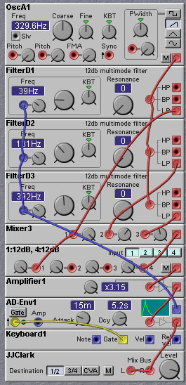
The patch shown below uses two self-resonant F-filters (classic filters) with their resonant peaks slightly separated (controlled by an LFO). A wavewrapper is used to add some harmonics to the sinusoidal output of the filters.
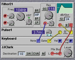
A soft attack can be generated without an envelope generator by using a filter with a resonance control input, and connecting the note gate signal to the resonance input. When the note gate is low, the filter resonance will be too low to support oscillation. When the gate goes high, the filter will begin to self-oscillate, but will take some time to reach its full amplitude.
The patch shown below implements this idea. We use the E-filter, as this provides a control input for the resonance level. Unfortunately, the E-filter does not self-oscillate, so we add a little bit of extra positive feedback (via the mixer) to make the filter self-oscillate.
Resonant filters can also make good sources of drum sounds. They need not be self-oscillating, but just have a high enough resonance level so that they "ring" for a while. The following patch shows this. The resonance is set to a fairly high level and the filter input is connected to a pulse derived from the note gate. The pulse causes the filter to ring. The higher the resonance level, the longer the ringing period. The filter rings for longer times at low cutoff frequencies than at high, so we adjust the resonance level with the note output to compensate.
The same ringing resonant filter technique can be applied to the generation of envelopes.
There are two basic structures to be used when combining filters - serial and parallel. We will begin by discussing serial filter structures. In a serial filter structure, filters are connected in chains, with the output of one feeding into the input of another.
We can make filters whose cutoff slope changes with frequency. For example, we can have a filter whose slope starts out as 12dB and then increases to 24dB. This is done by having a 12dB filter followed by a 24dB filter, with the cutoff frequency of the second filter being higher than that of the first. The effect of this type of filter is subtle compared with a normal 12dB filter but can be useful when you want a 12dB filter sound, but also want to reduce the buzziness caused by the very high frequency components.
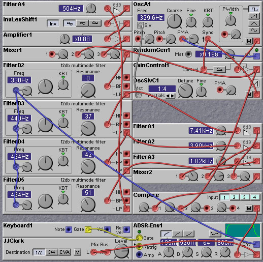
Perhaps ones of the best uses of serial structures is to alter the character of a filter's resonance. For example, one can construct a 'two pole' 12dB filter with a serial connection of two 6dB filters. Resonance can be obtained by feeding back the output (inverted) to the input. One can also obtain a resonant 12dB filter by stringing together four 6dB filters in series, feeding the output of the fourth filter back to the input, but taking the overall filter output only after the second filter. This will result in a 12dB filter with a resonant characteristic different than the first type of 12dB filter. The resonance characteristics can also be altered by modifying the feedback path. Putting filters, delays, or distortion elements in this path will all change the sound. The following patch allows a comparison between the resonance of the different Nord Modular filters, as well as to a custom filter constructed using four 12dB filters, with a feedback path, and output taken from the first 12dB filter. You can hear that the filters with the feedback taken from the higher order sections (beyond the 12dB point) all have a more pronounced resonance than the simple 12dB filter.
Serial structures are also useful for adding in multiple resonances to the filter's frequency response. We can do this by stringing together a number of resonant filters in series. Each filter should have a different cutoff frequency. This will result in a falloff that is more rapid than any filter taken alone, but will also result in multiple resonance peaks. This is useful for implementing 'body' resonances, such as found in physical instruments. Unlike real instruments, we can shift these 'body' resonances dynamically, with LFO or Envelope control signals, for example.
By using a set of filters in parallel (with each filter having the same input, and summing their outputs), one can obtain spectral characteristics different than that of the common second order resonant filter. For example, connect two lowpass second order filters with slightly different cutoff frequencies. Use an intermediate-to-high resonance level on each filter. The slightly different frequency components that are emphasized by the resonant peaks will interfere with each other, producing a beating or phasing sound. This effect is similar to that obtained with serially connected filters, but without the drawback of increasing the cutoff slope. Thus the resonant peaks can be stronger than in the serial configuration.
Parallel structures can be used to adjust the slope of the cutoff region. The non-static filter modules provided in the Nord Modular come in only 12, 18 and 24 dB varieties but we can construct filters with cutoff slopes that fall in between these values. This is done by combining filters in parallel that have different cutoff frequencies. As one filter drops off, there will be a corresponding reduction in the overall spectrum, but some of the other filters will still be passing these frequencies, so that the overall falloff rate is less than the individual filters. An example is shown in the following patch, where a (more-or-less) non-static 6dB filter is constructed from three 12 dB filters. As the input signal frequency passes the cutoff frequency of the filter with the lowest cutoff, the amplitude will start to drop off, but the other two filters will still be passing this frequency. As the signal frequency passes the cutoff of the filter with the next highest cutoff frequency, the signal amplitude will again start to drop, but some of the signal will still be passed by the third filter. Finally, when the signal frequency passes the cutoff of the third filter, the cutoff slope will be that of the third filter, 12dB. Thus the overall effect is of a filter with a reduced falloff rate over a certain range of frequencies. One can get an increased accuracy and increased range of applicability by using more filters, with cutoff frequencies closer together.
One common use of parallel filters is to split a sound into various frequency bands and process them separately, then recombine them. For example, you can distort the separate signals by differing amounts. The Roland SE-70 has a band chorus which breaks the sound into two bands (low pass and high pass filter) and allows different chorus settings to be applied to each band. Another possibility is to use phase shifters for each band. A good way to get a nice wide stereo sound is to direct different frequency bands to the left and right outputs. Some examples of this can be found in the chapter on effects.
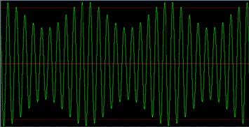
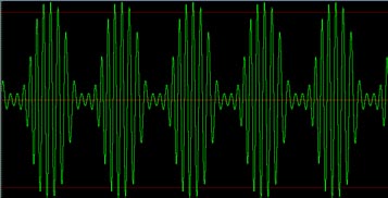
The graph below shows this effective amplitude modulation. The graph shows the output of a second order filter in response to a 1KHz sinusoidal input. The cutoff frequency control is being fed with a 100Hz sinusoidal input. The different plots depict different modulation levels, which translates into different cutoff frequency ranges. The nominal cutoff frequency is set to 1KHz.
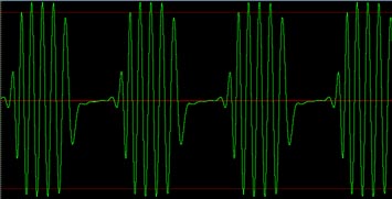
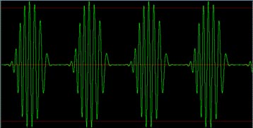
In the next graph, the modulation level is fixed, and the frequency of the input sinusoid is varied. As the frequency of this sinusoid moves from the center of the range of variation of cutoff frequency to the edge of the range, the effective amplitude modulation shape changes from a rounded square wave to a pulse wave. The modulation level was set to 25 in producing these graphs.
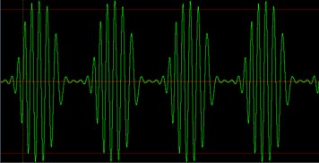
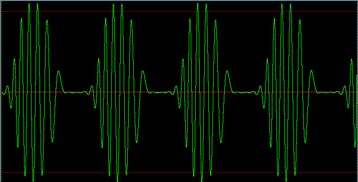
Finally, the next graph shows the effect of varying the filter cutoff slope from 18 dB/octave to 24 dB/octave. As the slope gets gentler, the shape of the amplitude modulation becomes rounder. In obtaining these graphs an input frequency of 1KHz was used, with a modulation level amount of 25.
The following patch implements audio rate filter cutoff modulation. Play around with this patch, changing the filter order (and therefore the slope of the filter cutoff), the filter type (from lowpass to highpass), and the filter resonance setting. Also try changing the input waveform type.
(Those of you with some background in signal processing theory may be wondering how it is that a completely linear system (which the filter is, even if we can modulate its cutoff frequency) can generate harmonics? The reason is that the system is time-variant. A linear time-variant system can generate harmonics, just as a non-linear time-invariant system can. It is only linear time-invariant systems that do not generate harmonics. You should also note that a ring-modulator is also a linear system (or, more precisely, a bilinear system). Doubling the amplitude of (one of) the inputs doubles the amplitude of the output. The ring modulator is a time-variant system, however, from the perspective of one of the inputs.)
One way in which to provide a better approximation to analog filters is to vary the resonance with the cutoff frequency. For example, the Moog classic filters do not have a constant resonance. Their resonance decreases significantly when their cutoff reaches and goes below about 130Hz. The Modular Moog filters do not self-oscillate below that frequency. Another aspect of true analog filters is that they have nonlinearities (changes in response as the input signal amplitude changes) that can cause distortion, or creation of harmonics, in the output. Finally, the properties of true analog filters change over time, primarily due to variations of component values resulting from changes in temperature. These slow variations cause subtle changes in the response of the filter, and are a big part of the "analog" sound.
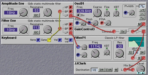
The following patch includes an emulation of an analog filter. It uses explicit feedback to implement resonance, rather than using the resonance control of the Nord Modular filter modules. This allows us to insert a clipping distortion in the feedback path, which models one of the most common causes of distortion found in analog filters. This approach to implementing resonance also has the by-product of reducing resonance as the cutoff frequency drops (or increasing resonance as cutoff frequency increases). Clipping is also added after each filter, to emulate the saturation of the analog filter stages. To accentuate the analog feel, we add small random variations to the filter cutoff frequencies, and to the clipping levels. Finally, portamento is added, to give the patch that classic synth sound!
Rob Hordijk has developed a very nice sounding "analog" style filter. His filter avoids the "buzzy" sound produced by many digital resonant filters. The buzziness arises because digital oscillators contain a relatively large amount of energy above 10kHz. Most analog oscillators have less energy in this region, as the analog circuitry itself filters part of it away. Imagine a sawtooth set to 200 Hz, therefore having overtones 200 Hz apart from each other. This means that in the area between 10 kHz and 20 kHz there are 50 overtones present, all crowded together within a single octave! When using, for example, 3 slightly detuned oscillators you're talking about 3 * 50 = 150 overtones all in that one high octave, and all phasing fast with each other. The amplitudes of these overtones are very small, but there are a lot of them and very high sounds are perceived quite well, so there is a distinct buzz in the high. If the cutoff frequency is set to this area the buzziness is increased even more at high resonance levels. The resonance band of a 12 dB filter is a bit broader than that of a 24 dB filter, so the 12 dB filter suffers a bit more from the buzz.
The problem with this buzz is that it can mess up those other sounds that have by nature lots of energy in the same band, notably hihats and cymbals and some dipthongs in the vocals. Thus it is a good practice to filter everything above 10kHz away from all instruments when there are hihats and cymbals in the rhythm track, or if you use vocals from someone with a clear voice. Otherwise these hihats and the s's and t's will drown in the high of the other instruments. Its even worse if the 10kHz+ area gets in a reverb with a very bright tail. That will start to produce lots of noise.
For most synth sounds, especially strings, its not the 10kHz+ area which is important, but the area between 3.5kHz and 10 kHz. So filtering away all above 10kHz but slightly emphasizing the 3.5 to 8 kHz area greatly improves the warmth and depth of stringsounds. A single 6 dB LP filter set to 10kHz won't do the job, the cutoff frequency should be set to 2.5 kHz or less to effectively remove the buzz. Even the cutoff frequency of a 24 dB filter should be set to something like 5kHz. But in both cases you would also lose part of the important 3.5 to 8 kHz area. The most useful solution is to use a dipfilter with a notch around 12 kHz.
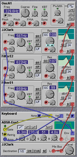
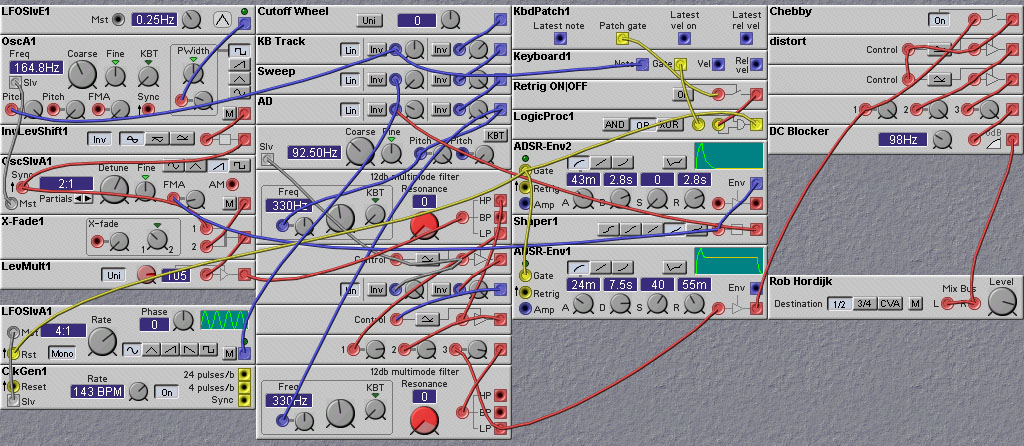
The filter is composed of two 12 dB filters that are cascaded to get a
24 dB filter. On the first filter a little bit of the HP output is
mixed to the LP output. This is tuned by a MasterOsc module. As it
apparently needs some bizarre overexponential control to get
everything right, the grey signal is raised to the power of two and
mixed with the grey signal to control the amount of HP. This creates a
notch at the top end of the spectrum, which does three things:
1) it attenuates the very high end, making the filter less
"buzzy ".
2) it reduces the resonance at the top end of the spectrum relative to
the rest of the spectrum, especially at high resonance settings. This
also makes the sound less buzzy.
3) the notch increases the filter slope slightly.
The messing about with that grey signal is just to keep the notch at the right place, which is tuned to taste by ear.
The second 12dB filter increases the filter cutoff slope to 24 dB. The feedback from the LP output of the second filter increases the bottom end of the spectrum, giving the sound a little bit more guts.
This filter can give good analog bass sounds with even a single sawtooth oscillator.
By filtering away a conflicting band in one of the sounds, especially if that band is emphasized in another sound, you can get much more control. In fact thats what most of postproduction is about and why multiband compressors have become so important. And why professional records sound so good. In well-produced recordings there is hardly ever a moment when a sound is soundwise conflicting with another sound, instead they all seem to emphasize each other to get that snappy drive. Rob Hordijk suggests using the shaper module to make the filter envelope signal reverse exponential. That way the filter stays a bit longer in the higher regions and the env doesn't have to sweep the filter above 10kHz, where all the horrible aliasing noise and hiss lives.
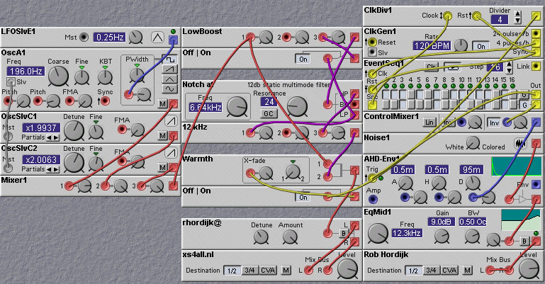
To get a good idea of how the presence of a notch in the filter response improves the sound, listen to the following patch for a couple of minutes. The patch includes a string-like waveform generator and a hi-hat sound. Without the notch on the strings the sound is 'tense' and the HH drowns in the stringsound. With the notch present, the sound is open and the tension is gone.
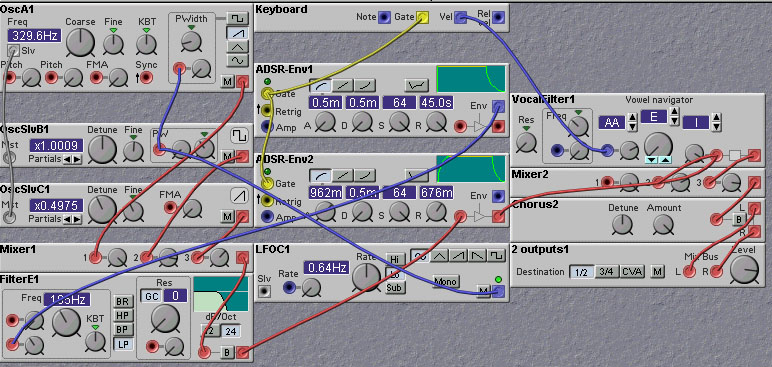
In listening to this patch there is also a slight formant effect that you can hear. If the sound is slightly more like 'aah' or 'uuh' it is generally felt as pleasant, whereas if it sounds more 'ooh' or 'iih'-ish then it has a bit more tension. The 'uuh' formant makes the sound neutral, an 'aah' effect asks for attention, 'ooh' makes it severe and 'iih' is like a conclusion. This has much to do with harmonicity, an obscure subject at first, but basically if too many overtones of different sounds and notes start to conflict with each other it starts to feel tense. One can use this to good effect in constructing string patches. Add a vocal filter module to the output and use it to add expressiveness or "emotion" to the sound. For example, use key velocity to modulate the vocal filter from "AA" through "UU" to "OO". Thus, at low velocities the sound will be mellow, while at high velocities the sound will be more tense. This is illustrated in the following patch:
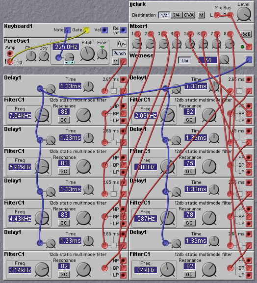
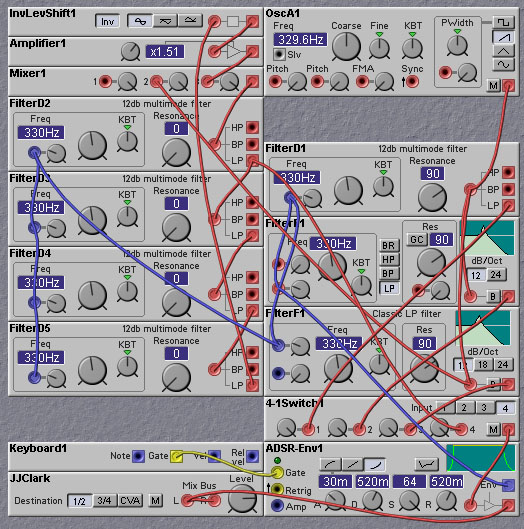
Much of the 'analog' sound of classic synthesizers was created by small differences in the filters' pole frequencies due to component tolerances. A big feature of the Nord Modular is that it is no problem at all to combine a number of filters in all sorts of combinations. For example, the following patch illustrates the use of a custom filter structure. Four 12dB lowpass filters are strung together in a serial arrangement. A feedback path is formed from the output of the final filter in the chain back to the first. A static lowpass filter is inserted at the end of the feedback path to limit the resonance at high frequencies that would otherwise cause the sound to become very buzzy. The outputs of three of the serial filters are fed into static lowpass filters, which provide some additional filtering and also introduce some phase shift. These three signals are then summed together to provide the final filtered result. The input waveform comes from a synced sawtooth. The resulting sound is reminiscent of a bassoon.