 About FM and DX7
 About FM and DX7
Working with FM synthesis and altering the converted Patches on the Nord Modular, some background information is welcome. First of all Rob Hordijk's Workshop about the issue is a must to read. He explains the different types of FM on the Nord Modular.
Yamaha uses the word Operator instead of Oscillator. In fact the Operator is more than just a wave generating tool.

In the Nord Modular an Operator is constructed out of three modules:
Each Operator is constructed this way, what ever it's a Modulator or Carrier (In which case the Envelope controls the total output)
For what reason has Yamaha's DX7 a structure of six Sine Operators, as other Yamaha synth only work at four? In one of the 'Thread Articles' Rob Hordijk answers this question:

[...] But when generating two, three or four 'bands' of the spectrum with a particular more or less steady timbre and mix their volumes by envelopes, much more natural timbre developments can be achieved. And that is why Yamaha chose a total of six sine waves in the DX7, now e.g. three groups of two sine waves can create three parts of the timbre, the fundamental part to create a distinct pitch sensation, the somewhat higher 'formant' area to create the basic instrument formant' character and a high or noisy brightness area as the brilliant top of the icing. Giving these all their own envelopes in time makes a relatively easy way to create all sorts of interesting 'natural'-sounding sounds. And of course there are more possibilities of arranging the six sine waves, the 32 algorithms. Each algorithm is meant to be good in synthesizing a particular class of sound/instrument.
The clue is always not to dynamically change the modulation depths too much (to avoid unnatural timbre developments), but to create separate 'spectrum bands' and give these their own envelopes and relative amplitude over the keyboard range. This explains why the DX7 is designed the way it is with all its envelopes and key/velocity scaling.
But using only four sine wave oscillators limits the way of working just described. And that can be heard, some very nice DX7 sounds are not convincingly made with only four operators. [...]
Con sized description of the behavior of harmonics using FM modulation
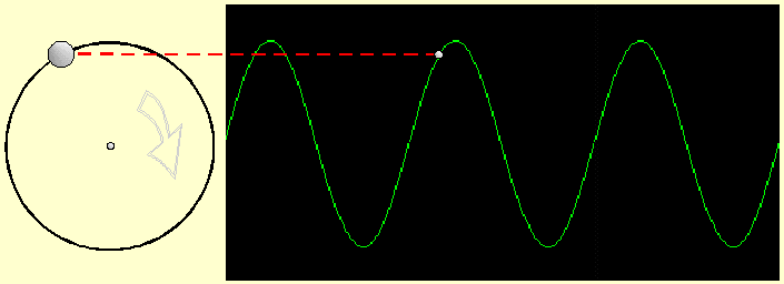
A sine wave can be seen as the result of a with a constant speed turning wheel with a at the rim a fixed point - in most examples a tungsten light bulb - which, observed from aside, looks like to go up and down. At the top and the bottom the light bulb appears to move slower and plotted in a diagram as a function of time as sine wave is constructed, as the next illustration shows.
Using PM can be imagined as the light bulb is attached to another wheel which is turning in speed of the modulating frequency, which can result in:
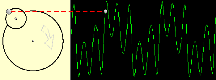
The amount the modulating signal is making the result wave form 'swinging' outside its un-modulated form is called 'deviation (d) The Index is calculated by the ratio d/M, in which M is the modulator frequency. The ratio C/M, frequency Carrier divided by frequency Modulator is the second parameter to be important in FM synthesis. In practice the Index is controlled by the FMB Knob together with an Envelope shaper controlling the Amplitude in a dynamic way and the FM ratio is controlled by the setting of the Oscillator frequency.
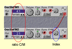
NB in this illustration the ratio is 1:2 (C is half M)
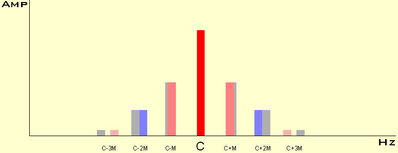
The FM ratio controls which side bands (harmonics) at each side of the Carrier frequency are generated and the Index controls their relative amplitude. The later is illustrated in the following diagrams.
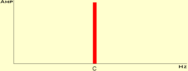
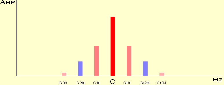
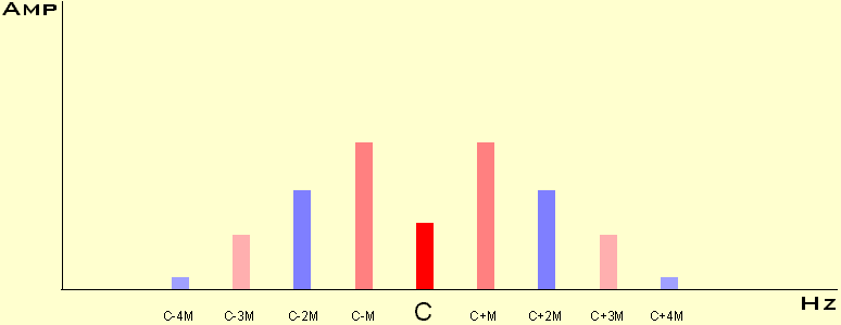
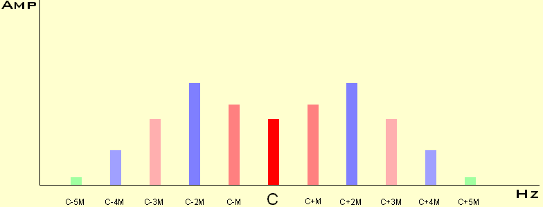
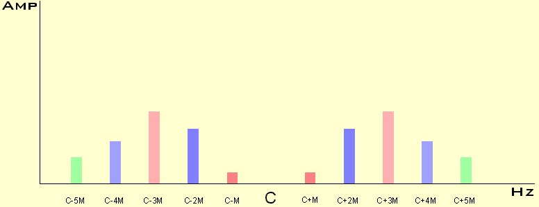
Notice when the Index increases the Carrier frequency is decreasing, increasing a little and vanishing completely.
In more scientific publications these diagrams are calculated by Bessel functions, but... I'm not sure everybody is interested in that ;-)
If the FM ratio will be changed to values not belonging to the natural figures (e.g. 1:1.2), those famous enharmonic tones are created, so useful in metal and bell like sounds. It's seems logical the side bands will move a little away from the Carrier frequency, here visualized by the grey color:
