Outputs:
Pulse, Triangle, Sawtooth
Panel Controls:
PWM - pulse width modulation amount
FINE - fine pitch offset, roughly 1.2 octave range
COARSE - coarse pitch offset, roughly 5 octave range
LIN FM - linear FM amount
Exp FM - exponential FM amount
PW - pulse width
Size - 3U x 12HP (128.5mm x 60.6mm)
Power Supply Current (max) 35.8mA at +12V, 30.7mA at -12V
Frequency Range: 15 Hz to 7 KHz
Linear Frequency Range (linearity error less than 1%, average 0.13%):
30Hz to 4.2KHz
(7+ octaves)
 Schematic image
Eagle PCB software schematic file
Frontpanel design file
XR2207 datasheet
Schematic image
Eagle PCB software schematic file
Frontpanel design file
XR2207 datasheet
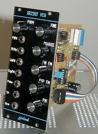
The 2207 has a linear timing current to frequency characteristic, so an exponential converter is needed. I used a standard matched bipolar transistor pair implementation of the converter, as shown in the schematic. I used an LM394 as the matched pair, for the simple reason that these devices were available from Digikey. I used a Panasonic ERA-S33J102V surface mount resistor for the temperature compensation resistor. These have a 3300ppm temperature coefficient, close to the coefficient of the matched transistor pair. They are quite inexpensive, only 75 cents CDN each in lots of 10 from Digikey. They are also very tiny and a bit of a pain to solder. I epoxied the tempco resistor onto the top of the LM394 metal can.
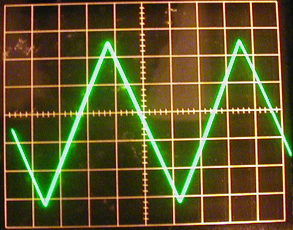
The XR2207 produces triangle and square waves. The triangle wave is very high quality. The square wave, on the other hand has a rounded top, probably because of the external pullup resistor. I didn't want to make the pullup resistance too small, to keep the power supply current from getting too high. A sawtooth waveform was generated by offsetting the triangle wave and then switching its polarity on the alternate phases of the squarewave. This is done by shorting the +ve input of the summing opamp with an NPN transistor. The resulting sawtooth has a slightly rounded top.
I tried a number of different sync methods but none worked very well. The timing capacitor voltage is bipolar, so one cannot simply short it with a bipolar transistor. Doing so gives a sort of soft-sync. A symmetric MOSFET or JFET might do the trick; I didn't try such an approach. In any event, my prototype doesn't have a working sync capability.
I actually don't bring the XR2207 square wave output to the front panel. Instead I generate a pulse signal by feeding the triangle wave into a comparator with an adjustable reference input. This allows pulse width modulation. The pulse waveform has slightly rounded corners, unfortunately.
An oscilloscope photograph of the triangle waveform produced by the VCO module
is shown in the figure below.
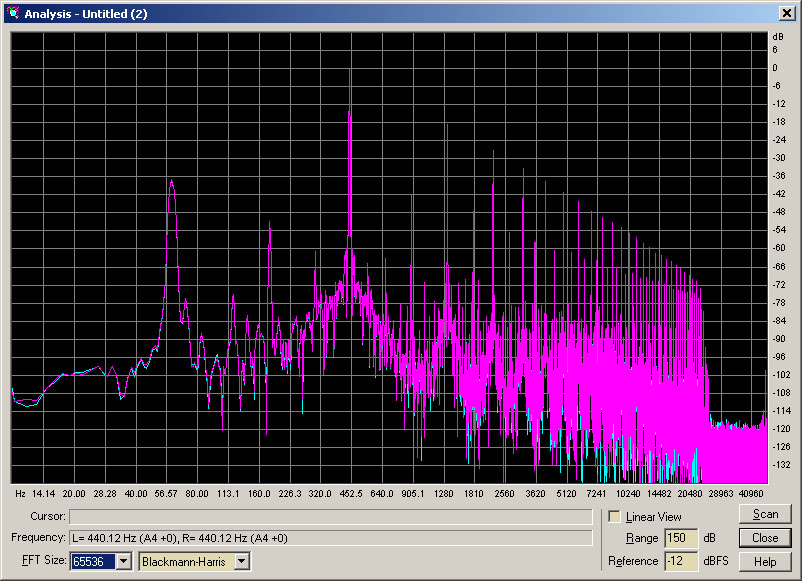
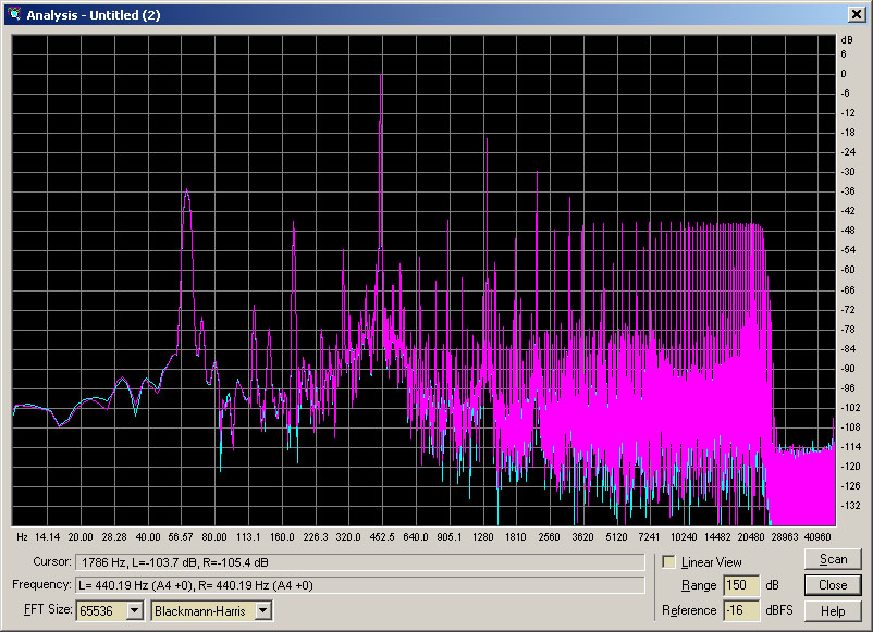
To get an idea of the comparative quality of the 2207 triangle waveform with the Doepfer A-110 VCO triangle waveform, look at the spectrum plots shown below. These plots were produced by the CoolEdit program on a 60-second sample of a 440Hz triangle waveform, with a sampling rate of 48,000 samples/per second in an Event Gina 20-bit sound card. It can be seen that the harmonics of the 2207 triangle fall smoothly out to the limits of the sampling rate of the soundcard, whereas the harmonics of the A-110 VCO stop falling in amplitude around 3620 Hz. There is a low-level Square-wave even harmonic sequence present, at about 36dB down (extrapolating the sequence back to the fundamental) from the Triangle wave odd-harmonic sequence. This might be leakage from the square wave output, or might be coming from the power supply lines in response to the different current draws on the alternate phases of the square wave. In both waveforms one can see a 60Hz (hum) component that is about 36 dB below the fundamental. This is probably from the power supply. My complete system was drawing approximately 645mA, which is close to the rated limit of the Doepfer power supply (650mA).
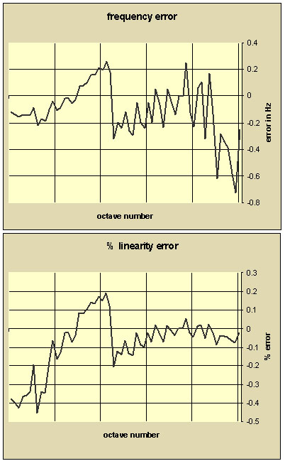
The VCO is fairly linear. As the graphs below show, the linearity error is less than 0.2% over most of a 5 octave range from 30 to 960 Hz (and actually is that good over a 7 octave range). The frequency error is mostly less than 0.2 Hz over this range, with an increase to 0.6 Hz error at higher frequencies (the frequency error will give the beat frequency with an exact oscillator).