Back
to the research list page
Akihiro Sato's SLIP Hopper page |
|
This page describes my Master's thesis research done in Ambulatory Robotics Lab, Centre for Intelligent Machines, McGill University. The topic is a biomechanically-inspired planar hopping robot named the SLIP Hopper. This project was supervised by Prof. Martin Buehler, who is now with Boston Dynamics. Table of Contents: Quick Overview Motivation & Background Dynamics Model Control Experimental Platform Numerical Simulation Results (Data & Videos) Experimental Results (Data & Videos) Publication Frequently Asked Questions Highlights: Simulation Video 1 (MPEG, 0.4 MB) Experiment Video 1 (MPEG, 7.3 MB) Experiment Video 2 (MPEG, 1.2 MB) |
Quick Overview |
|
The complex musculoskeletal system of a running animal on horizontal surfaces act essentially like a simple pogo stick. My research was focused on the development of a robotic pogo stick, i.e. a planar one-legged hopping robot with only one motor. A feasibility study was performed using numerical simulation. The experimental platform was designed and built based on biomechanics. Simulation and experimental data demonstrated periodic and robust stability. Running was achieved at 6.7 leg lengths per second, which is, to date, the fastest dimension-less speed for a single-legged robot. |
Motivation & Background |
|||||||||||||||||||||||||
|
- Robotic fast terrestrial mobility that can negotiate rough terrain is aimed at, i.e. running of a legged robot is studied; -
Inspired by biomechanics, in the last two decades, the Spring-loaded Inverted Pendulum
(SLIP) model has been
extensively used as a reduced-order model in analysis and control of running
legged robots. However, the SLIP
model itself has never been implemented in a robot and validated
experimentally before; - The simple SLIP
architecture with a single actuator should be sufficient for the running
motion on level surfaces only.
This allows the focus on the fundamental of running motion. - The use of only one actuator
simplifies physical design and implementation. (In return, analysis and control can be more involved due
to the resultant underactuation); - SLIP Hopper is the first robot of its kind in terms of kinematics and the number of actuators as shown below: Table: Comparison to previous work
|
|||||||||||||||||||||||||
Dynamics Model |
|
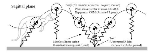
The SLIP model is used as the dynamics model in numerical simulation. The SLIP Hopper, the experimental robot, is designed based on the SLIP-model features and advantages. Spring-loaded Inverted Pendulum (SLIP) model:
- One degree of
freedom (DOF) of leg rotation joint is actuated, and the other DOF of leg
extension joint is unactuated with compliance (i.e. the system is
underactuated). Only one control input is available
for speed control and hopping height control; - Entire
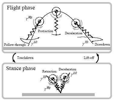
dynamics model is a hybrid of two models of the flight and stance phases; Flight dynamics is
easily approximated by a ballistic trajectory, while stance dynamics is
non-integrable and difficult to understand analytically; - Equations of motion
for the center of mass (COM) are derived for each of the flight and stance
phases, using Lagurange equation. Running Kangaroo
and the SLIP model
|
Control |
|
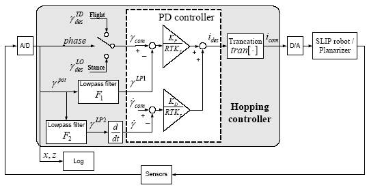
- PD controller is used to regulate leg angle via hip motor torque. This allows leg trajectories to have smooth changes in direction and velocity.
Hip motor torque generated by PD control regulates leg motion
- Phase-dependent switching control is used (the desired angles are switched at the phase transition events: touchdown and lift-off);
Diagram of implemented control code: mainly consisting of the desired angle switching and PD controller
|
Experimental Platform |
|
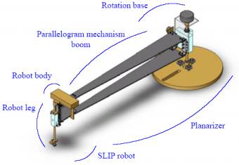
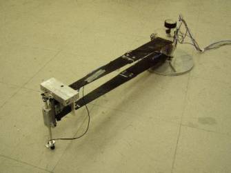
Mechanical system structure: -
Robot has an actuated hip
joint and a passive prismatic joint with a spring for bouncing (energy
store/restitution); - Motion of the robot body is constrained by a
planar-constraint mechanism "planarizer" to approximate planar
motion and to restrict pitch motion.
Isometric view
of the CAD design of the robot with the planarizer
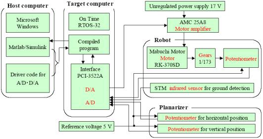
Actual robot with the planarizer Computer & electrical system structure: - Robot
is tethered to the target computer via an interface card, which operates both
D/A and A/D conversions; - A control signal is sent from D/A to a motor amplifier, and sensor signals are acquired from A/D.
|
Numerical Simulation Results (Data & Videos) |
|
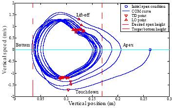
Simulation Video 1 (MPEG, 0.4 MB), Presented in IROS 2004, etc. - Start from a reasonable condition (initial condition in neighborhood to the steady state). Simulation Video 2 (MPEG, 0.3 MB) - Robust recovery from a disturbed condition (a negative forward speed at apex). Phase plot of the vertical position of the COM: -
The combination of the two dynamics forms a closed
orbit and repeats tracing the same pattern periodically, i.e. a limit cycle
is generated; - Motion on concern (i.e. vertical motion) is periodic at steady
state.
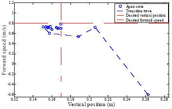
Transition plot (plot of subsequent apex states): - Apex state converges to the desired sate from an initial
condition (IC) with a large error; - Hopping motion would be robust to the disturbance that brings
the robot state to a converged IC.
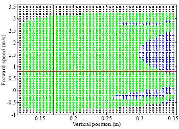
Region of attraction
(collection of converged initial conditions in green): - Region of attraction is large
(i.e. robustness is high) without adaptive control; - Convergence is assured in the neighborhood
of steady state.
|
Experimental Results (Data & Videos) |
|
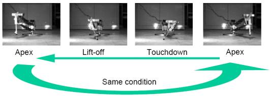
Experiment Video 1 (MPEG, 7.3 MB) Filmed Jun. 26, 2003. Presented in IROS 2004, etc. - Infinite running starting from an initial condition. Experiment Video 2 (MPEG, 1.2 MB) Filmed Nov. 30, 2003. Published in the CD-ROM of IROS 2004. - Close view of one cycle of steady running in high frame-rate video. Snapshots from high frame-rate video: - Dynamical state at one apex
returns to the same state at the next apex; - Continuous running from the infinite
repetition of this gait cycle.
Hopping motion
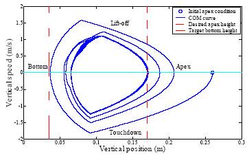
from one apex to the next Phase plot of the vertical position of the
COM: - Limit cycle is generated, i.e. periodicity is
demonstrated. - Close correspondence to the phase plot with
the simulation is shown.
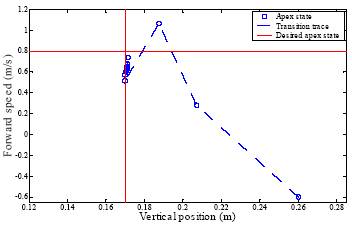
Transition plot: Apex state converges to the
desired sate from an IC with a large error.
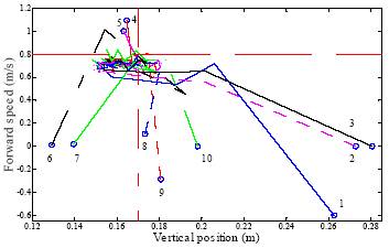
Region of attraction: -
Large region of attraction (i.e. high robustness)
is indicated, based on 10 tested initial conditions.
|
Publication |
|
Refereed international conference proceedings: - A. Sato and M. Buehler, "A Planar Hopping Robot with One Actuator: Design, Simulation, and Experimental Results," IEEE/RSJ 17th Int. Conf. on Intelligent Robots and Systems (IROS 2004), pp. 3540-3545, 2004. - A. Sato, "Simulation of a one-legged hopping robot with phase plane stability," 18th IASTED Int. Conf. on Modelling and Simulation (MS 2007), pp. 112-117, 2007. - A. Sato, "Simple switching control for hybrid dynamics of a planar hopping robot," Ninth IASTED Int. Conf. on Control and Applications (CA 2007), pp. 63-68, 2007. |
Frequently Asked Questions |
|
Q1: What kind of robot is the SLIP Hopper? A: The SLIP Hopper
is a planar one-legged hopping robot.
This robot is developed in order to study some principles of running
dynamics that can be achieved by running legged robots. To simplify the analysis, only one
leg is considered and only the COM motion in the Sagittal plane is
considered. The word
"planar" means that the robot can move in 2D, not in 3D, because
the robot motion is constrained by a mechanism named the planarizer. Q2: What is the main idea? A: Many planar
one-legged hopping robots in the past have two actuators. A popular arrangement is one actuator
for the hip rotation to control forward speed and the other for the leg
thrust to control hopping height.
Those robots were successful, so it is a good idea that my research
goes further. I aimed to
control both forward speed and hopping height using only one actuator. The SLIP model is exploited and its
passive spring in the leg is a key to allow it to run with one actuator. The results of my research have
already shown that there exists a particular running gait that achieves a
desired forward speed and a desired hopping height at the same time and that
is very robust. Q3: How can the robot run forward by using only one
actuator? How can it jump upward
without a thrust actuator in the telescopic leg? A: The actuator is
at the hip joint so that the robot can rotate the leg. This leg rotation propels the robot
body pivoted at the ground contact of the leg toe so that it goes forward and
upward. The leg also has a
spring so that the robot does not have to push the body upward against the
ground using a thrust actuator. Q4: Is there any actuated joint in the planarizer? A: No. All the
joints in the planarizer are passive (in another word, unactuated). In the entire platform (the robot and
planarizer), the only one actuated joint is the hip joint between the robot
body and the robot leg. Q5: Why is the body of the SLIP model a point-mass? Why is the leg massless? Isn't it unpractical? A: You're
right. Some hypotheses of the
SLIP model are not practical. It
is because the model was originally introduced to explain animal biomechanics
a few decades ago and after that, it was developed by Raibert to analyze and
control more complex robots than the SLIP model itself. The center of mass (COM) and the
ground contact point of the foot were connected by an imaginary line, and the
motion of the two points and the line were described using a spring. The SLIP model was originally not
meant to be realized as an experimental platform. Q6: Doesn't the hip torque spin the body? Should't the robot's pitch
rotate? A: No. In the ideal model, the body is
a point mass (and has no moment of inertia as a result), and the leg is
completely massless (and has no moment of inertia as a result). That means that the leg can be
rotated to any angle you want without spinning the body at all. This
theoretical model first appeared in the field of experimental biomechanics to
explain animal locomotion, and the examination of the model was one of the
research purposes here. Thus, no rotation of the body was desired. In my simulation, the leg is massless, but its moment of
inertia is considered so that I could check if the leg angle at touchdown can
properly be set to a certain desired angle in time by using the limited
performance of the motor installed on my experimental platform. One way to make it possible to
simulate this is to set the inertia of the body to be big enough. On the experimental platform, the center of mass is not
located at the hip joint.
However, the boom-planarizer constrains the pitch motion of the robot
body so that we can assume that the center of mass coincides with the hip
joint. Since the boom fixes the
robot body, the hip torque doesn't spin the body. Q7: Is it ok if posture control is not considered? A: It is fine with
the SLIP Hopper. The
posture control of the body is not considered since the original SLIP model
by definition has the center of mass coincident with the hip joint axis, i.e.
the body did not have the moment of inertia or pitch motion to be
considered. Thus, the posture
angle is not defined. The SLIP
Hopper is an experimental implementation of this model. Therefore, the robot has a constraint
in its pitch motion. I am aware that this constraint is not practical for
applications to humanoid robots, for instance, but this constraint is just a
result of sticking to the original SLIP model. Recently, some interesting papers on rigorous mathematical
analysis of the SLIP model have been published and they take into
consideration the offset between the hip joint and the center of mass and the
pitch posture motion of the body part.
To my knowledge, they haven’t shown the full properties of that kind
of model. If it is possible to
choose arbitrary hopping height and forward speed and the model is still
stable, then the hopping height, the forward speed, and the body posture in
the sagittal plane will be able to be controlled using only one
actuator. I would like to have
robots with such mechanical structures and controllers for more practical
applications in the future. Q8: Is the SLIP Hopper capable of hopping in place? A: Unfortunately,
no. The robot doesn't have
any actuator to thrust, i.e. the leg cannot push off the ground in the
direction of leg extension. Q9: Did you do any simulation of vertical hopping in
place? A: No. Q10: Is there any way to make the SLIP Hopper hop in
place using a different controller? A: Basically,
no. It is not possible for the
SLIP Hopper to keep hopping in place if the leg angle is fixed
vertically. An external
force has to be input vertically, but it can't be. The leg has to have some angle to the vertical and be rotated
in the stance phase in order to have the vertical element of the ground
reaction force created by a hip torque.
As a result of this leg motion, the robot cannot stay in place. It might be possible to make it hop
in place by using a certain combination of a leg angle and a hip torque that
produces external forces such that the horizontal elements of the forces are
all cancelled out. Q11: Can the SLIP Hopper run without the boom-planarizer? A: No. It is because the SLIP Hopper cannot
stabilize lateral-plane motion.
For now, pitch motion is not controlled either, but a pitch controller
can be relatively easily implemented in the future since it is a matter of
software, not hardware, if a control law is derived. Q12: Do you think you can construct a robot that can hop
around without a boom-planarizer by adding another motor at the hip joint to
control lateral motion? A: Yes. Actually, the Leg Lab at CMU/MIT
constructed that kind of hopping robot two decades ago using two rotational
actuators at the hip and a thrust actuator in the leg (three actuators in
total). If the results of the
SLIP Hopper are used, no thrust actuator will be needed (two actuators will
be needed in total) unless vertical hopping is required. Q13: Does the boom-planarizer have any counterbalanced
mass on the opposite side of the boom?
Does the planarizer have a bungee to lift up the robot or boom? A: No, not at all. Q14: The robot motion in the videos looks excellent. Is it reproducible and repeatable? Or are you showing the only trials that were successful? A: The running
motion was 100% repeatable without failure, as long as the initial condition
was inside a reasonable range (i.e. inside the large region of
attraction). For all the trials,
the motion converged to a neighborhood of a desired steady-state within a few
seconds. Q15: How did you produce the initial conditions? A: They were produced by releasing/throwing the robot in
the air by hand. The first apex
state is considered as the initial condition. Q16: Why is there a coke can in the video of experiment? A: Because it can
show the size of the robot.
It's not an advertisement. |
|
If you have any
comments/suggestions/other questions, please feel free to send an e-mail to
me at |
Copyright © 2002-2007 by Akihiro
Sato. All rights reserved.