PATTERN RECOGNITION
Course
Project for cs644
A
Simple Method for Computing General Position in Displaying Three-Dimensional
Objects
(Paper
by Tomihisa Kamada and
Satoru Kawai,
1987)
#Abstract #Introduction
#Method #Algorithm
#Applet #Conclusion
NOTE: THE APPLET WORKS WITH INTERNET EXPLORER BUT
NOT NETSCAPE4 FOR SOME REASON (sad but true..I guess ie won this
one)
1.0
Abstract
The
following is an implementation of a method proposed by Kamada and Kawai
in their paper to compute the "nicest" viewing angle for a 3D wire
frame object. This viewing angle is "nice" as it is intended
to provide the viewer with the maximum shape information.
2.0
Introduction
The
projection of a 3D image onto a 2D canvas is controlled by parameters such
as the View Reference Point (VRP), the View Up vector (VUP), the View Plane
Normal (VPN), the Center of Projection (COP) (in perspective projection)
and the projection direction (in parallel projection). The VRP is
a point on the projection plane which when combined with the VPN define
the projection plane. The VUP vector is another axis orthogonal to the
VPN along the projection plane. Ultimately one has to choose the
VRP such that one obtains the desired visual effects and obtains the shape
of the objects being viewed. Kamada and Kawai present a method of
choosing the VRP in such a manner that the general appearance of
the objects in view is easily obtainable. The term general here
means that the shape information of the original 3D objects is represented
to the maximum extent on a 2D plane. For example, we want a cube
to be seen as a cube and not a square upon projection to a 2D plane.
3.0
Method
The
method described in the paper is applicable only to parallel projections
where the projection direction is perpendicular to the projection plane.
The problem of finding the VRP thus resorts to computing the projection
direction vector.
Consider projecting a
line in 3D onto a 2D plane. If the projection results in a point,
all the information about the line is lost. This happens when the
projection direction is parallel to the line. Similarly for two lines
in 3D, the worst case happens when both lines are projected onto a single
line in 2D. This happens when the projected direction is parallel
to the plane containing the two lines. This worst case scenario can
be avoided however by the non-zero angle between the projection direction
and the plane. In fact, the greater the angle is, the more geometry
regarding these two lines can be understood in the resultant projection.
See diagram below (top half).
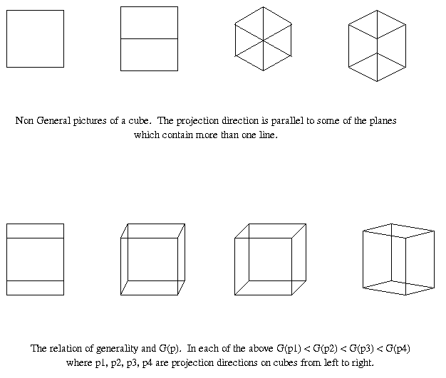 FIGURE 1 depicts cubes seen from non general views (top)
and general views (bottom)
FIGURE 1 depicts cubes seen from non general views (top)
and general views (bottom)
-
DEFINITION 1:
Let L be the set of lines of an object
-
DEFINITION 2:
Let T be the set of unit normal vectors of the planes which contain more
than one element of L. Note that this is does not say the
set of normals for the faces.
-
DEFINITION 3:
Let p be the unit vector of the projection direction which
we want to compute.
The idea behind the paper
is precisely to compute this vector p.
-
DEFINITION 4:
Let G(p) = min(|p.t|) ,where t is an element
of T, be the generality measure of a vector p.
Since p and
t are both unit vectors above, their dot product is merely the cosine of
the angle between them. So if you compute the angle between all the
vectors t in T and p, G(p) expresses the cosine
of the maximum angle between p and t as the smaller the cosine
of an angle, the larger that angle (NOTE the absolute value).
In order to maximize
the generality of the most non general parts, the maximin criterion is
used. It can be said that the larger G(p) is, the more
general p is (see diagram above, bottom half). This
is true as the value of G(p) increases, the maximum angle
between p and t becomes smaller; in other words the minimum
angle between p and planes which contain more than one line
becomes larger.
We seek the most general
vector that maximizes G(p). Hence the general position
problem can be reduced to the maximin problem of determining p
which maximizes G(p), i.e.,
max min (|p.t|)
where |p| = 1 and t is an element of T
3.1
Algorithm
Consider taking all the
normals from T (note that these are not just the normals of the faces of
the wire frame object but also include normals to any plane containing
two or more edges) and joining them such that they all originate at the
same point. The tips of these normals all lie on the surface of the
unit sphere. So the problem of finding p can be viewed
as the problem of finding the smallest circle on a unit sphere that encloses
all of t or -t where t is an element of T. The unit vector
p which maximizes G(p) is located precisely
at the center of this circle. By examining this unit sphere from
a view directly incident onto the center of this computed circle (i.e.
looking down into the sphere along the line drawn from the center of the
sphere along p to the camera) the viewer is guaranteed to
see the most t's, and hence have the best impression of the wire frame
image.
If a unit vector p
maximizes G(p) then there are at least two elements t1
and t2 which satisfy
G(p)
= |p.t1| = |p.t2|
This is due to the fact
that the smallest enclosing circle problem goes through at least two or
three points on the surface of the unit sphere. When its goes through
only two points, the line joining these two points is the diameter of the
circle.
The algorithm is therefore:
-
Compute all enclosing circles
and their respective centers
-
Find the smallest circle
from these, the center of which gives desired p
More formally follow the
algorithm
link to see the full algorithm (taken verbatim from the paper)
4.0
Applet
The
applet works in the following manner:
-
Given an input file consisting
of points and edges, it proceeds to compute p and map the
3D wire frame onto the 2D awt canvas. The points are specified as:
pt label x,y,z where the user is free
to choose the label, and x,y,z are the coordinates of the point.
NOTE: since no bounding box is used in the projection, values of
points which fall beyond the size of the canvas will not be drawn.
This is not a severe restriction as the canvas is large. Once the
points are inputted, edges have to be specified to connect the points.
An edge is specified in the following manner: edge
label1 label2 where label1 and label2 conform to the labels
of two inputted points.
-
Once the wire frame is constructed,
the applet proceeds to find all the normals T. Once all the normals
are there, p is computed from them and the wire frame is
mapped to a 2D plane specified by p. Note that the
camera is always placed looking into the wire frame down the line drawn
from the center of the wire frame along the direction specified by p.
Once a 2D parallel projection is obtained, it is drawn onto the canvas
Using
the applet:
-
To run the demos click the
choices button and choose one of the demos. Once the demo is chosen the
user can enter (into the small text field by the buttons) any view thats
been precomputed e.g. if 30 views are computed the user can enter any view
number from 0 to 29. Since the algorithm is O(n4) the
more complicated the wire frame in terms of the number of normals computed,
the longer it takes. For the star please be very patient as
it takes a few minutes.
-
To input your own wire frame,
first enter the points into the text field provided (using the format given
above) then enter the edges (using the format given above). Once
everything is entered, click the compute button. Note that
to see what you have entered, type show
into the text field and see the result in the java console provided by
your browser. This process can be very tedious so another alternative
is to mail me the file of the wire
frame you wish to see and I can add it to the demos.
-
The rotate button obviously
rotates the wireframe. It does so in a manner such that the entire
object is seen. The stop rotation button kills the rotate thread
whereas the pause one suspends the thread.
-
If you want the source code
please mail me.
5.0
Conclusion and future work
Needless
to say the algorithm is very slow. However it can be modified to
a more complicated algorithm which works in O(n3) on average
and O(n3 *log n) in worst case.
Stay
tuned to see the next version which will show all the best views computed
(as p is not necessarily unique) as well as giving the user
the ability to choose progressively better/worse views. Also a spinning
wire frame which halts to give the best view would be nice.
6.0
Acknowledgments
Thanks
to Professor Godfried
Toussaint who helped decipher the algorithm and taught the course superbly.
Also thanks to Richard Unger
who effectively taught me this Java thing and provided the command parser
for text input for the code.